
4 layers95 × 95 mm
Cube motherboard
willem-pennings/balancing-cube
A cube that balances itself in a corner or edge using reaction wheels
52 parts1.1kGPL-3.0

 dinordi/RetroGame1
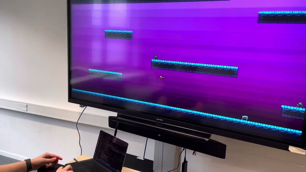
Saga of Sacrifice is a 2D-platformer where the player traverses several levels to defeat his nemesis, a samurai.
RetroGame is an open-source printed circuit board by dinordi, from the dinordi/RetroGame repository on GitHub. It is a 2-layer board of 73.7 × 83.8 mm with 6 parts on 62 nets, routed with 97 tracks and 0 vias.
It is built around the ESP32-S3-DEVKITC-1-N8. Its parts include 1 IC and 1 connector. It belongs with the ESP32 boards of this library.
Retro Game - Saga of Sacrifice
.. raw:: html

Saga of Sacrifice is a 2D-platformer where the player traverses several levels to defeat his nemesis, a samurai.
The game runs using a ESP32-S3-DevkitC v1.1 and a Basys3 FPGA.
Video Showing Gameplay
.. image:: https://img.youtube.com/vi/o0PvoIunmNI/maxresdefault.jpg :alt: IMAGE ALT TEXT HERE :target: https://www.youtube.com/watch?v=o0PvoIunmNI
Getting Started
Welcome to Saga of Sacrifice! See the Hardware Documentation_ for a high-level overview,
and the documentation's Setup_ to get the game running.
.. start_include_here
.. _project-resources:
Hardware Documentation
The KiCad files can be downloaded from the Docs/KiCad folder.
Scheme <https://github.com/dinordi/RetroGame/blob/main/Docs/KiCad/images/retrogame.pdf>_
PCB Coloured <https://github.com/dinordi/RetroGame/blob/main/Docs/KiCad/images/retrogame-brd.svg>_
PCB Back <https://github.com/dinordi/RetroGame/blob/main/Docs/KiCad/images/PCBAchter.pdf>_
PCB Front <https://github.com/dinordi/RetroGame/blob/main/Docs/KiCad/images/PCBVoor.pdf>_
+------------------+----------------------------------+ | GPIO pin | Function | +==================+==================================+ | GPIO 6 | Joystick left | +------------------+----------------------------------+ | GPIO 4 | Joystick right | +------------------+----------------------------------+ | GPIO 7 | Joystick up | +------------------+----------------------------------+ | GPIO 5 | Joystick down | +------------------+----------------------------------+ | GPIO 16 | Green button | +------------------+----------------------------------+ | GPIO 15 | Red button | +------------------+----------------------------------+ | GPIO 9 | Black button | +------------------+----------------------------------+
Setup
The game runs on a ESP32-S3-Devkit-C v1.1 using the Zephyr RTOS. v3.5.0. Windows 11 is tested no guarantee is given for any other OS. For building the esp code West version: v1.2.0 is used. For compiling the FPGA code Vivado 2023.2 is used. Plug the VGA cable into the FPGA, headphonejack into the aux output and the micro usb cables into the ESP32 and FPGA. That should be all for the setup, the software is already flashed.
DFPlayer mini
If at any point the music/SFX need to be changed. The SD Card folder structure must be maintained!
Software
The game is written in C++, classdiagram is available in the Docs folder. The source code for the game is well-commented, providing clear explanations for the functionality of each function. With some research and understanding of these comments, you should be able to modify and adapt the code to suit your needs.
Changing Sprites
explanation how to change sprites with Piksel and which dimensions we use (15x15 etc) and also how to upload them to the FPGA.
Changing text
Q: How to fix empty screen/weird boxes are all over the screen?
A: Restart ESP32 using reset button or unplugging from power. If that does not work, restart FPGA by pressing the restart button.
Q: Why isn't there any audio playing?
A: Check if both SD cards are seated properly in DFPlayer mini's. Also check if the aux cable is connected to an amplified speaker. The aux connection port could be a little janky, so check if the GND pin makes connection to the PCB.
Q: Can't flash or can't see the COM port for the esp?
A: Make sure you have the micro usb cable in the port labeled 'uart' on the esp. Also installing a driver is needed to get the COM port to work.
Download the driver in the github and follow the following link starting at "Manually Install Device Drivers on Windows". Manually Install Device Drivers on Windows_
When you browse for the driver, select the driver folder from the git.
| 🌐 Zephyr Project Website_
.. .. _Zephyr Project Website: https://www.zephyrproject.org .. _Manually Install Device Drivers on Windows: https://www.groovypost.com/howto/install-device-drivers-manually-on-windows-11-10/ .. _Hardware Documentation: https://github.com/dinordi/RetroGame/tree/main/Docs/ .. _Getting Started Guide: https://github.com/dinordi/RetroGame/tree/main/Docs/ .. _FAQ: https://github.com/dinordi/RetroGame/tree/main/Docs/
| Qty | Value | Footprint | References |
|---|---|---|---|
| 2 | ~ | Library:DFPlayer Mini | DFPlayer mini Music, DFPlayer mini SFX |
| 1 | AudioJack3 | Connector_Audio:Jack_3.5mm_CUI_SJ1-3523N_Horizontal | Stereo Output |
| 1 | Conn_01x03_Socket | Connector_PinSocket_2.54mm:PinSocket_1x03_P2.54mm_Vertical | FPGAConnector |
| 1 | ESP32-S3-DevKitC | PCM_Espressif:ESP32-S3-DevKitC | U1 |
| 1 | Screw_Terminal_01x10 | TerminalBlock_Phoenix:TerminalBlock_Phoenix_MKDS-1,5-10-5.08_1x10_P5.08mm_Horizontal | J3 |
willem-pennings/balancing-cube
A cube that balances itself in a corner or edge using reaction wheels

jazzmonger/Traeger-PID-Controller
Traeger Smoker/Grill Controller based on an

ohasanov-hbrw/tribit32-advanced
A tri-microcontroller, overengineered GameBoy Advance clone. More value was given to the controls and the exterior look, which is cool!


FIPATECH/CDFR26_PAMI
Open source firmware and PCB for a differential mobile robot (PAMI) based on ESP32-S3 - Coupe de France de Robotique

dnhutchins/ETC_Express_Reverse_Eng
The ultimate goal of this work is to develop an interface to use the control surface from a legacy ETC Express 24/48 lighting controller as a modern EOSNomad compatible programming and fader wing.

heckler/esphome-device-configs
Configuration definitions for local ESPHome files
It measures 73.7 × 83.8 mm and has 2 copper layers, 1.6 mm thick.
6 parts, built around the ESP32-S3-DEVKITC-1-N8. The full list of its parts is on this page, with links to each part's symbol and footprint where PCBKit's library has them.
From the dinordi/RetroGame repository on GitHub, at the commit this page was made from: the board is Docs/KiCad/retrogame/retrogame.kicad_pcb and its schematic Docs/KiCad/retrogame/retrogame.kicad_sch. PCBKit opens the board in the browser, with nothing to install.
Its repository states no licence, so its author keeps all rights: ask dinordi before reusing the design.