2 layers27 × 8.8 mm
 dimhoff/ser401027
UART controllable SI4010 based tunable OOK/FSK RF transmitter
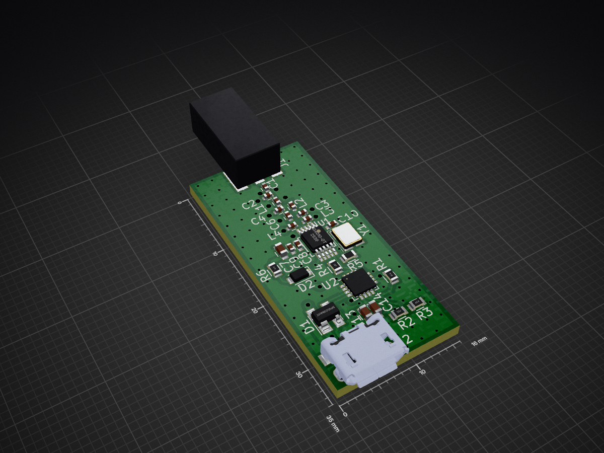
Ser4010 is an open-source printed circuit board by dimhoff, from the dimhoff/ser4010 repository on GitHub, published under the BSD-3-Clause licence. It is a 2-layer board of 16 × 35 mm with 39 parts on 30 nets, routed with 176 tracks and 118 vias.
It is built around the CP2102N-A01-GQFN20R and SP0503BAHTG. Its parts include 14 capacitors, 8 connectors, 6 resistors, 5 inductors and 2 ICs. It belongs with the interfaces and adapters and radio and wireless boards of this library.


The SER4010 module is a tunable Sub-GHz RF OOK/FSK transmitter based on the Silicon Labs Si4010 chip. It is controlled from a PC through standard UART based serial connection. The encoding of the frames is fully done in software on the PC, while the actual modulation and sending is offloaded to the module. This allows for great flexibility in the transmitted signals, while having accurate signal timing. While having the full programming capacity of a normal PC platform.
The Si4010 chip can operate in a frequency range of 27 to 960 MHz. Although the actual frequency band it can effectively operate on depends on the antenna/matching network. Within its operating band the transmitter can be tuned to allow matching the receivers frequency, causing better reception/range.
The SER4010 firmware is controlled using a 3.3 Volt serial(RS-232 like) connection.
The pins are mapped as follows:
The following communication parameters are used:
Suggested is to use a 3.3 volt compatible USB-to-serial adapter, like a FT232 or CP2102. The module can also be directly connected to a RaspberryPi, or similar.
The hardware/ directory contains a PCB design for a USB connected SER4010 device. This hardware is still under development and is untested testing.
Note: This is only useful if you plan to develop on the firmware. Else use the precompiled firmware from GitHub releases section.
For compiling the SER4010 firmware the Silicon Labs IDE and Si4010 Example Programs are required. These are both free downloads from the Silabs website. Note that the Silicon Labs IDE only runs on MS Windows.
First copy some files from the Si4010 Example Programs archive into the SER4010 source:
Next start the Silicon Labs IDE and open the ser4010/firmware/ser4010/bin/ser4010.wsp workspace. It should now be possible to compile the project. This will generate the ser4010.hex firmware file in the ser4010/firmware/ser4010/out/ directory.
Run the following to compile the libser4010 library and tools:
# cd build
# cmake ../
# make
The software uses /dev/ttyUSB0 by default as serial port. If your module is connected to a different serial port you can change the default serial device to use by using the following cmake command instead of the above one:
# cmake ../ -DDEFAULT_SERIAL_DEV=<your serial port>For example for the Raspberry PI use '/dev/ttyAMA0' when the module is connected to the internal serial port.
TODO: Extend chapter...
You have to load the SER4010 firmware into the Si4010 module. Either by programming it once into the non-volatile NVM memory. Or by loading it after every reboot into the modules RAM.
See the si4010prog tool
Make sure the serial port to which the module is connected does not have a serial console or any other software using it. Else the communication will get scrambled.
Note that the Raspberry PI 1/2 have a bootloader that always outputs a string to the internal serial port at boot. This causes a communication-out-of-sync error the first time you run any of the ser4010 tools. Just try again.
To use the internal serial port of the Raspberry PI 3 you must disable the Bleutooth. This can be done using the pi3-disable-bt Device tree overlay.
All SER4010 tools provide a '-d' option to specify which serial port to use. This option is only needed if you didn't specify the correct serial port at compile time, see Compiling the Software, or when using multiple modules. Valid arguments for the '-d' option are for example /dev/ttyS0, /dev/ttyUSB0 or /dev/ttyAMA0.
To test if the communication with the module works you can use the ser4010_test_comm utility from the tools/ directory. An example of a working module output:
# build/tools/ser4010_test_comm
Communication OK
The tool will either output 'Communication OK' or an error. In case of error verify you properly connected the device (switched TX/RX?). And verify you are using the correct serial port and no other software is using the serial port.
The ser4010_dump tool can be used to dump the current module configuration. This is mainly for debugging. You don't have to manual change any of these configuration parameters since all other SER4010 tools will automatically chose the correct parameters for there application.
Example output:
# build/tools/ser4010_dump
Device Info:
------------
Device Type: 0x0100
Device Revision: 3

ODS settings:
------------
bModulationType: OOK (0)
bClkDiv: 5
bEdgeRate: 0
bGroupWidth: 6
wBitRate: 1100
bLcWarmInt: 8
bDivWarmInt: 5
bPaWarmInt: 4

PA settings:
------------
fAlpha: 0.000000
fBeta: 0.000000
bLevel: 60
bMaxDrv: 0
wNominalCap: 256TODO:
TODO:
| Qty | Value | Footprint | References |
|---|---|---|---|
| 2 | 0.1uF | Capacitors_SMD:C_0603 | C12, C14 |
| 2 | 16nH | silabs_0402:C_0402 | L3, L4 |
| 2 | 4.7uF | Capacitors_SMD:C_0603 | C11, C13 |
| 2 | 6.8pF | silabs_0402:C_0402 | C2, C4 |
| 1 | 1.8pF | silabs_0402:C_0402 | C6 |
| 1 | 100 | Resistors_SMD:R_0603 | R4 |
| 1 | 18nH | silabs_0402:C_0402 | L1 |
| 1 | 1k | Resistors_SMD:R_0603 | R1 |
| 1 | 1nF | Capacitors_SMD:C_0402 | C8 |
| 1 | 2.2uF | Capacitors_SMD:C_0603 | C7 |
| 1 | 2.7pF | silabs_0402:C_0402 | C5 |
| 1 | 22.1k | Resistors_SMD:R_0603 | R2 |
| 1 | 220nH | silabs_0402:C_0402 | L5 |
| 1 | 270pF | Capacitors_SMD:C_0402 | C9 |
| 1 | 270pF | silabs_0402:C_0402 | C1 |
| 1 | 3V3 | Measurement_Point_Round-SMD-Pad_Small-Labeled:Measurement_Point_Round-SMD-Pad_Small-Labeled | J3 |
| 1 | 4.3pF | silabs_0402:C_0402 | C3 |
| 1 | 47.5k | Resistors_SMD:R_0603 | R3 |
| 1 | 470 | Resistors_SMD:R_0603 | R6 |
| 1 | 56nH | silabs_0402:C_0402 | L2 |
| 1 | 5pF | Capacitors_SMD:C_0402 | C10 |
| 1 | C2CK | Measurement_Point_Round-SMD-Pad_Small-Labeled:Measurement_Point_Round-SMD-Pad_Small-Labeled | J5 |
| 1 | C2D | Measurement_Point_Round-SMD-Pad_Small-Labeled:Measurement_Point_Round-SMD-Pad_Small-Labeled | J6 |
| 1 | CP2102N-A01-GQFN20 | Housings_DFN_QFN:SiliconLabs_QFN-20-1EP_3x3mm_Pitch0.5mm | U2 |
| 1 | Conn_Coaxial | Adafruit-SMA_EDGELAUNCH:Adafruit-SMA_EDGELAUNCH | J1 |
| 1 | DNF | Resistors_SMD:R_0603 | R5 |
| 1 | GND | Measurement_Point_Round-SMD-Pad_Small-Labeled:Measurement_Point_Round-SMD-Pad_Small-Labeled | J7 |
| 1 | LED | Diodes_SMD:D_0805 | D2 |
| 1 | LFXTAL055915 | IQD_CFPX-180:Crystal_SMD_IQD_CFPX-180_4pin_3.2x2.5mm | Y1 |
| 1 | SP0503BAHT | TO_SOT_Packages_SMD:SOT-143 | D1 |
| 1 | Si4010-GT | Housings_SSOP:MSOP-10_3x3mm_Pitch0.5mm | U1 |
| 1 | USB_OTG | Amphenal_FCI_10118193-0001LF_USB_Micro-B:Amphenal_FCI_10118193-0001LF_USB_Micro-B | J2 |
| 1 | VBUS | Measurement_Point_Round-SMD-Pad_Small-Labeled:Measurement_Point_Round-SMD-Pad_Small-Labeled | J8 |
| 1 | VPP | Measurement_Point_Round-SMD-Pad_Small-Labeled:Measurement_Point_Round-SMD-Pad_Small-Labeled | J4 |
The 38 most common of 39 parts.
It measures 16 × 35 mm and has 2 copper layers, 1.6 mm thick.
39 parts, built around the CP2102N-A01-GQFN20R and SP0503BAHTG. The full list of its parts is on this page, with links to each part's symbol and footprint where PCBKit's library has them.
From the dimhoff/ser4010 repository on GitHub, at the commit this page was made from: the board is hardware/schematic/ser4010.kicad_pcb. PCBKit opens the board in the browser, with nothing to install.
Its repository publishes it under the BSD-3-Clause licence: you may reuse it on that licence's terms (keep the author's notice, and for a copyleft licence share your changes alike).


ConfusedHello/STorM32-NT
A fork of the STorM32 NT controller board for my own purposes.

jaival-bhatia/ESP32-C3-4-Layer-IoT-Development-Board
A custom-designed 4-layer ESP32-C3 IoT development board featuring USB Type-C, Li-ion battery management, environmental sensing, OLED display, and expandable peripheral interfaces.

vul-os/sirboard
Open hardware: 107 KiCad PCB designs — SMD-to-THT breakout adapters, ATTiny/ATMega/ESP development boards, and a 39-part sensor line on a common JST-SH connector.

fossasia/pslab-hardware
PSLab Hardware Design and Schematics https://pslab.io

