2 layers90 × 45 mm

 dilshan/6ch-af-preamplifier12
5.1 channel audio preamplifier
6ch preamp is an open-source printed circuit board by dilshan, from the dilshan/6ch-af-preamplifier repository on GitHub, published under the MIT licence. It is a 2-layer board of 151.3 × 50.8 mm with 126 parts on 96 nets, routed with 928 tracks and 53 vias.
It is built around the TL072, PT2258-S and LM317T, with the LM337T, BSS138 and BC817 among its other parts. Its parts include 44 resistors, 40 capacitors, 17 connectors, 9 ICs and 3 transistors. It belongs with the audio and music and lEDs and displays boards and the PIC boards of this library.


This project introduces a digitally controlled 5.1 channel audio preamplifier system. This amplifier is specifically designed to increase the gain of the multi-channel PC sound cards.
This preamplifier consists of six TL074/TL072 preamplifier stages and PT2258 electronic volume control. The input stage of this preamplifier consists of six TL074/TL072 buffer stages. The PIC16F886 microcontroller manages the PT2258 electronic volume control IC. All the volume levels and menu options are displayed on HD44780, 16×2 character LCD screen.
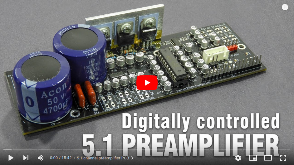
The provided PCB design contains a preamplifier, buffer stages, digital volume control circuit, driver circuit, and power supply unit.
The project was sponsored by PCBWay. The accurately configured PCB of this preamplifier can directly order from PCBWay through their website. The dimension of the PCB is 151.45 × 50.76mm.
This preamplifier is a certified open hardware project. All source codes, KiCAD design files, and compiled binaries are available at this repository.
The complete documentation of this project is available in the wiki section of this repository. The PCB Gerber files and compiled binaries are also available in the release section of this repository.
All the content of this project are distributed under the terms of the following license:

| Qty | Value | Footprint | References |
|---|---|---|---|
| 25 | 1MFD | Capacitor_SMD:CP_Elec_4x5.3 | C14, C15, C16, C17, C18, C19, C20, C23, C24, C25, C26, C27, C28, C29, C30, C31 +9 |
| 12 | 3.5mm Terminal | 6ch-opamp:3.50mm_PCB_Terminal | J6, J7, J8, J9, J10, J11, J12, J13, J14, J15, J16, J17 |
| 11 | 10K | Resistor_SMD:R_0805_2012Metric_Pad1.20x1.40mm_HandSolder | R10, R11, R12, R13, R14, R29, R30, R31, R32, R41, R42 |
| 7 | 22K | Resistor_SMD:R_0805_2012Metric_Pad1.20x1.40mm_HandSolder | R8, R33, R34, R35, R36, R43, R44 |
| 6 | 100K | Resistor_SMD:R_0805_2012Metric_Pad1.20x1.40mm_HandSolder | R21, R22, R23, R24, R37, R38 |
| 6 | 10MFD | Capacitor_SMD:CP_Elec_5x5.3 | C6, C7, C8, C9, C21, C22 |
| 6 | 1M | Resistor_SMD:R_0805_2012Metric_Pad1.20x1.40mm_HandSolder | R15, R16, R17, R18, R19, R20 |
| 6 | 2.2K | Resistor_SMD:R_0805_2012Metric_Pad1.20x1.40mm_HandSolder | R25, R26, R27, R28, R39, R40 |
| 5 | 0.1MFD | Capacitor_SMD:C_0805_2012Metric_Pad1.18x1.45mm_HandSolder | C1, C10, C11, C12, C13 |
| 5 | PCB-PAD | TestPoint:TestPoint_Pad_D2.0mm | TP1, TP2, TP3, TP4, TP5 |
| 4 | M3 | MountingHole:MountingHole_3.2mm_M3_DIN965_Pad | H1, H2, H3, H4 |
| 3 | 0R | Resistor_THT:R_Axial_DIN0204_L3.6mm_D1.6mm_P2.54mm_Vertical | R1, R2, R3 |
| 2 | 0.1MFD | Capacitor_THT:C_Disc_D10.5mm_W5.0mm_P10.00mm | C4, C5 |
| 2 | 1K | Resistor_THT:R_Axial_DIN0207_L6.3mm_D2.5mm_P10.16mm_Horizontal | R5, R6 |
| 2 | 390R | Resistor_THT:R_Axial_DIN0207_L6.3mm_D2.5mm_P10.16mm_Horizontal | R4, R7 |
| 2 | 4700MFD | Capacitor_THT:CP_Radial_D30.0mm_P10.00mm_SnapIn | C2, C3 |
| 2 | BSS138 | Package_TO_SOT_SMD:SOT-23 | Q2, Q3 |
| 2 | TL072 | Package_SO:SO-8_3.9x4.9mm_P1.27mm | U7, U9 |
| 2 | TL074 | Package_SO:SO-14_3.9x8.65mm_P1.27mm | U6, U8 |
| 1 | 16-pin 2.54mm Male Header | Connector_PinHeader_2.54mm:PinHeader_1x16_P2.54mm_Vertical | J2 |
| 1 | 2-pin Micro JST | Connector_JST:JST_EH_B2B-EH-A_1x02_P2.50mm_Vertical | J3 |
| 1 | 3.5mm Terminal | Connector_Phoenix_MC:PhoenixContact_MCV_1,5_3-G-3.5_1x03_P3.50mm_Vertical | J1 |
| 1 | 470R | Resistor_SMD:R_0805_2012Metric_Pad1.20x1.40mm_HandSolder | R9 |
| 1 | 5-pin 2.54mm Male Header | Connector_PinHeader_2.54mm:PinHeader_1x05_P2.54mm_Vertical | J5 |
| 1 | 5-pin Micro JST | Connector_JST:JST_EH_B5B-EH-A_1x05_P2.50mm_Vertical | J4 |
| 1 | 50K | Potentiometer_SMD:Potentiometer_Bourns_TC33X_Vertical | RV1 |
| 1 | BC817 | Package_TO_SOT_SMD:SOT-23 | Q1 |
| 1 | LM317T | Package_TO_SOT_THT:TO-220-3_Vertical | U2 |
| 1 | LM337T | Package_TO_SOT_THT:TO-220-3_Vertical | U3 |
| 1 | LOGO | 6ch-opamp:pcbway-logo | G*** |
| 1 | PIC16F886-IP | Package_SO:SSOP-28_5.3x10.2mm_P0.65mm | U4 |
| 1 | PT2258 | Package_DIP:DIP-20_W7.62mm_LongPads | U5 |
| 1 | W04 | Diode_THT:Diode_Bridge_Round_D9.0mm | D1 |
| 1 | uA7805 | Package_TO_SOT_THT:TO-220-3_Vertical | U1 |
The 125 most common of 126 parts.

dslmande/TR-808PSU
UNTESTED KiCad rebuild of the Roland TR-808 power supply board PS3116 in two versions: 230 V (PS3116-054) and 110 V (PS3116-051). Not manufactured, not safety-tested.

N4ch0VS/fuente-lineal-regulable
Diseño en KiCad de una fuente de alimentación lineal regulable, con esquemático, PCB y lista de componentes, pensada para obtener un voltaje de salida ajustable de forma estable.


andriish-hw/esp32-audio-streamer
A custom desktop audio streamer featuring a dual-ESP32 architecture designed for high reliability, dedicated audio processing, and low-latency hardware control.
It measures 151.3 × 50.8 mm and has 2 copper layers, 1.6 mm thick.
126 parts, built around the TL072, PT2258-S, LM317T and LM337T. The full list of its parts is on this page, with links to each part's symbol and footprint where PCBKit's library has them.
From the dilshan/6ch-af-preamplifier repository on GitHub, at the commit this page was made from: the board is design/6ch-preamp.kicad_pcb. PCBKit opens the board in the browser, with nothing to install.
Its repository publishes it under the MIT licence: you may reuse it on that licence's terms (keep the author's notice, and for a copyleft licence share your changes alike).