2 layers40 × 34 mm

 dillhicks/dilpad1
dilpad: Hotswap Numpad/Macropad with QMK Support
Dilpad is an open-source printed circuit board by dillhicks, from the dillhicks/dilpad repository on GitHub. It is a 2-layer board of 97.6 × 81.8 mm with 37 parts on 39 nets, routed with 170 tracks and 0 vias.
Its parts include 17 diodes, 2 switches, 1 IC and 1 connector. It belongs with the keyboards and input boards and the AVR (ATmega, ATtiny) boards of this library.
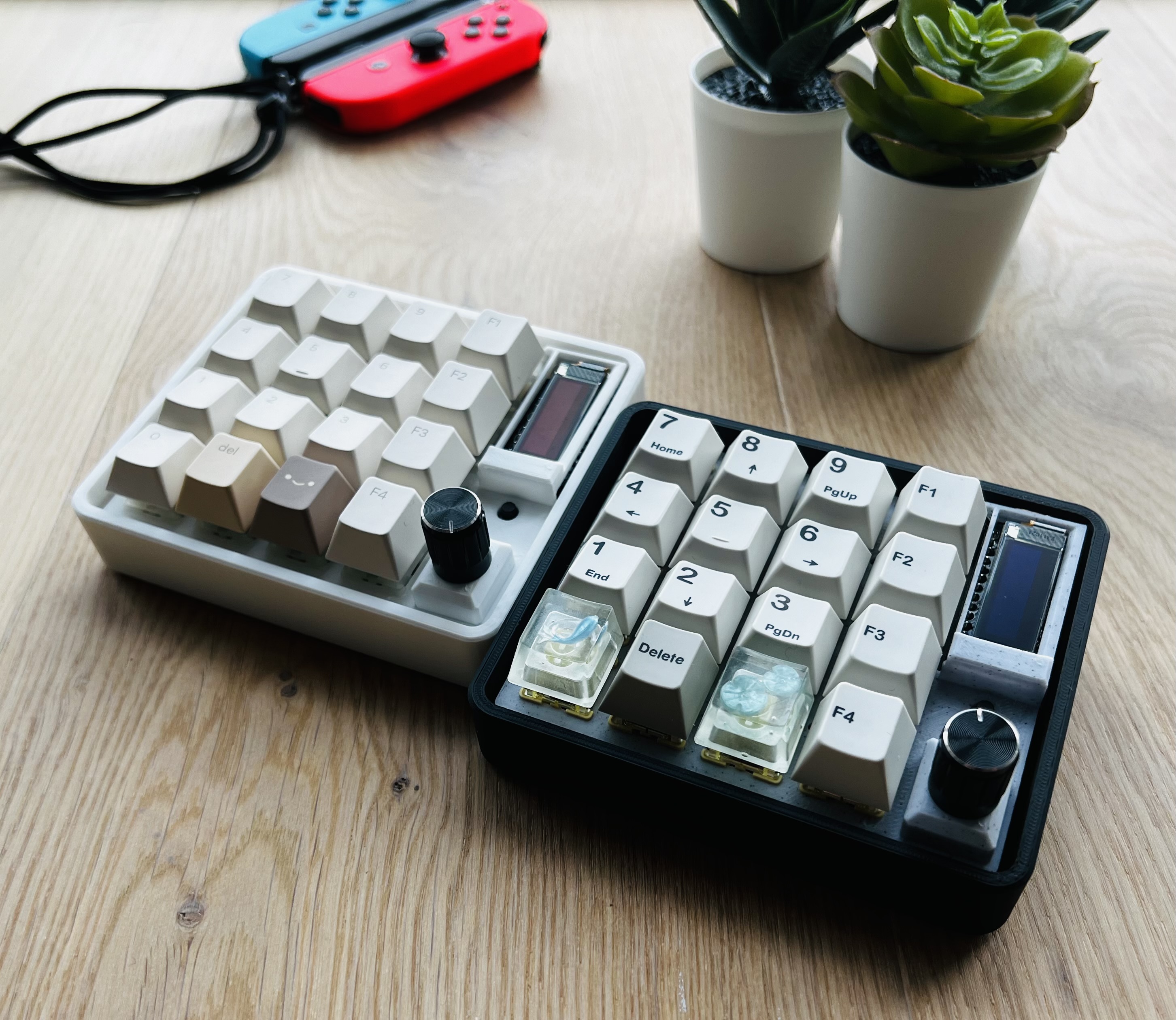
Dilpad is a simple, easy to build numpad that is loosely based on the Dumbpad. Initially created as a fork of the Dumbpad combo_oled, but adds hotswap switches, screw holes for mounting the PCB to the case, and moved everything to the right. It was decided at that point to simply make another board to learn how to build keyboards from scratch!
This board presents a great introduction to making keyboards, and soldering to those who are new. The dilpad also sounds surprisingly good with a plate/shroud and case that resonates well. The dilpad was also designed with a little bit more space to the edges of the PCB, which can open the doors for some interesting mounting options, such as gasket mounting if anyone wants to try that.
QMK & VIA Support
Hotswap Sockets
Rotary Encoder
Through-Hole Components: Designed for straightforward soldering.
The following components are needed to build the dilpad. Costs have been added for convenience (based off of 2024 Aliexpress prices)
| Component | Quantity | Approx. Cost for 1 dilpad ($) |
|---|---|---|
| Dilpad PCB | 1 | 2.5 |
| MX-style mechanical switches | 16 | 4 |
| Kailh CPG151101S11 hotswap sockets | 16 | 3 |
| MX-style keycaps | 16 | 2.5 (or use those leftover with your keycap set!) |
| 1N4148 diodes (through-hole) | 17 | 0.5 |
| Arduino Pro Micro or a pin-compatible ATmega32u4-based MCU | 1 | 3.5 |
| Component | Quantity | Approx. Cost for 1 dilpad ($) |
|---|---|---|
| EC11 rotary encoder with pushbutton | 1 | 1 |
| SSD1306 OLED | 1 | 2 |
| 6mm push button | 1 | .25 |
In total, it should cost less than 25 dollars, even cheaper if you decide to forgo the OLED and rotary encoder!
Soldering Iron
Flush Wire Cutters
Kapton Tape (to insulate the bottom of the OLED)
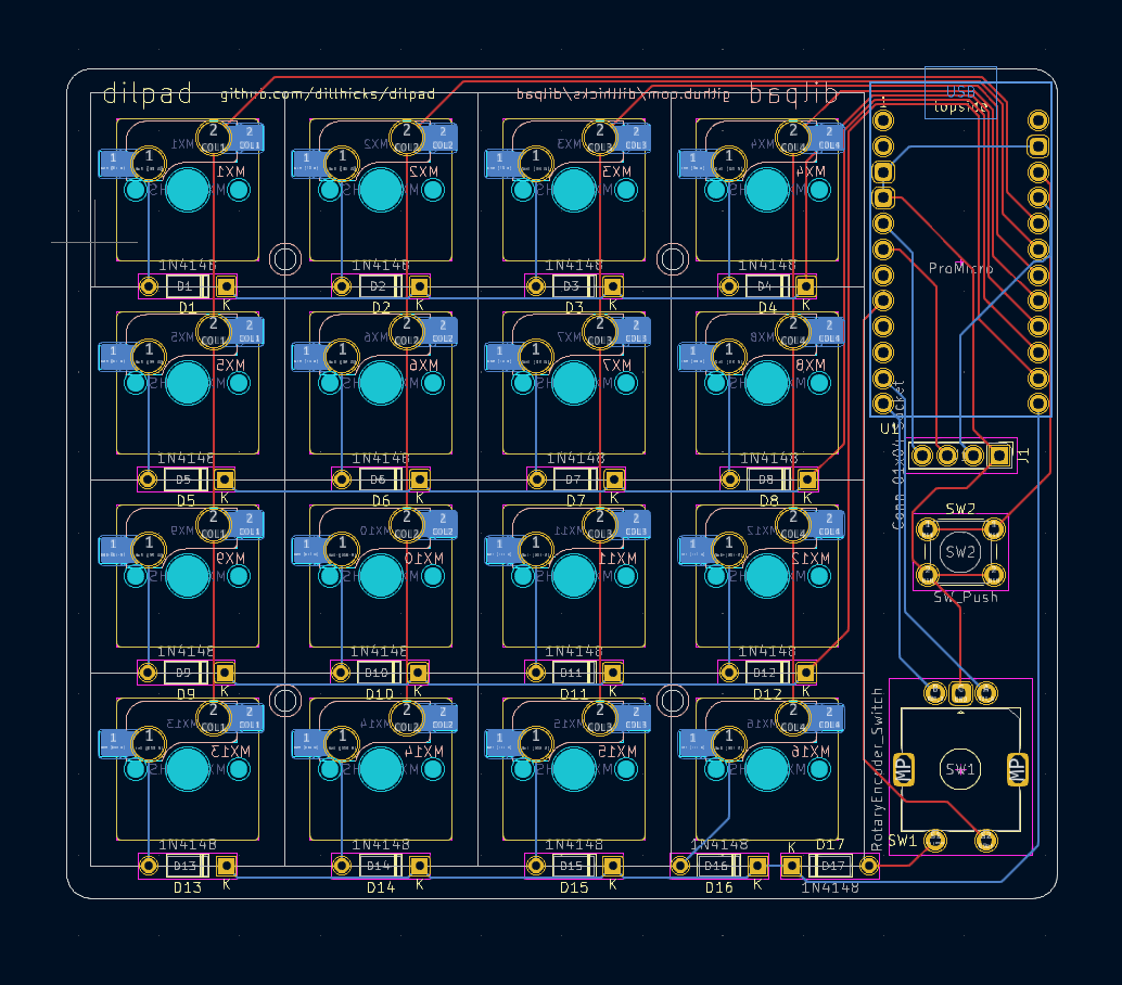
I reccomend to solder the components in the following order to the starting from the back side of the PCB:
Flash Your Firmware:
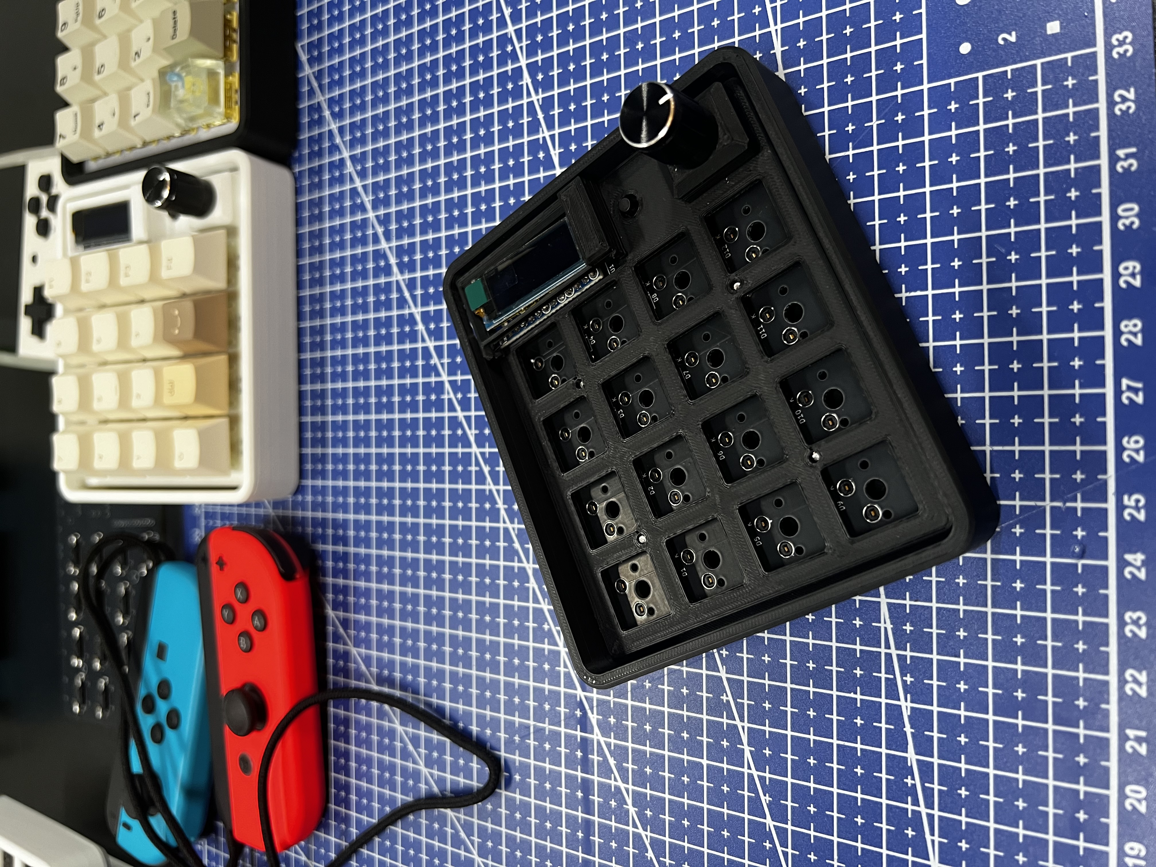
Add Firmware to QMK and VIA for official support
Make version of shroud without rotary encoder and oled
Add additional tools to OLED
| Qty | Value | Footprint | References |
|---|---|---|---|
| 17 | 1N4148 | Diode_THT:D_DO-35_SOD27_P7.62mm_Horizontal | D1, D2, D3, D4, D5, D6, D7, D8, D10, D11, D12, D13, D14, D15, D16, D17 +1 |
| 16 | MX_SW_HS | PCM_marbastlib-mx:SW_MX_HS_1u | MX1, MX2, MX3, MX4, MX5, MX6, MX7, MX8, MX9, MX10, MX11, MX12, MX13, MX14, MX15, MX16 |
| 1 | Conn_01x04_Socket | Connector_PinHeader_2.54mm:PinHeader_1x04_P2.54mm_Vertical | J1 |
| 1 | ProMicro | PCM_marbastlib-xp-promicroish:ProMicro_USBup | U1 |
| 1 | RotaryEncoder_Switch | PCM_marbastlib-various:ROT_Alps_EC11E-Switch | SW1 |
| 1 | SW_Push | Button_Switch_THT:SW_PUSH_6mm_H8mm | SW2 |
It measures 97.6 × 81.8 mm and has 2 copper layers, 1.6 mm thick.
37 parts. The full list of its parts is on this page, with links to each part's symbol and footprint where PCBKit's library has them.
From the dillhicks/dilpad repository on GitHub, at the commit this page was made from: the board is dilpad.kicad_pcb and its schematic dilpad.kicad_sch. PCBKit opens the board in the browser, with nothing to install.
Its repository states no licence, so its author keeps all rights: ask dillhicks before reusing the design.

hoglet67/RGBtoHDMI
Bare-metal Raspberry Pi project that provides pixel-perfect sampling of Retro Computer RGB/YUV video and conversion to HDMI

hackclub/OnBoard
💡 Join 1,000 teenagers and make your first PCB with a $100 grant!

FreeYourStream/freedeck-hardware
all the stuff you need to build your own FreeDeck

stuartpittaway/diyBMS
Do it yourself battery management system for Lithium ion battery packs/cells

Pwnsat/FlatSat
Flatsat v1.0 is a hardware based platform for aerospace cybersecurity research


vsfteam/vsf
Versaloon Software Framework -- a tiny preemptive-capable event-driven incremental software framework for embedded systems