2 layers140.5 × 30 mm
Type e
google/mozc-devices
Circuit diagrams and firmware source code for Gboard DIY keyboards
16 parts3kApache-2.0

 dh1tw/vna-testboard3
A handy PCB for experimenting and prototyping with Vector Network Analyzers
Sdr kits testboard is an open-source printed circuit board by dh1tw, from the dh1tw/vna-testboard repository on GitHub. It is a 2-layer board of 38 × 30 mm with 16 parts on 13 nets, routed with 14 tracks and 0 vias.
It belongs with the radio and wireless and sensors and measurement boards of this library.
I really like this small PCB testboard for prototyping and experimenting with my Vector Network Analyzers. SDR-Kits used to sell it as a complimentary item for the DG8SAQ VNA. Unfortunately, mine showed some wear and SDR-Kits doesn't sell the PCB / Testkit anymore. So I clone it.
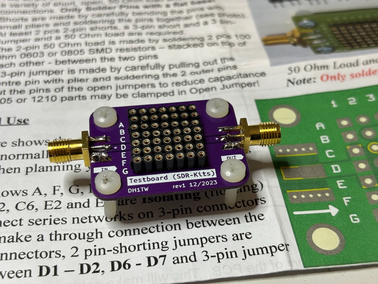
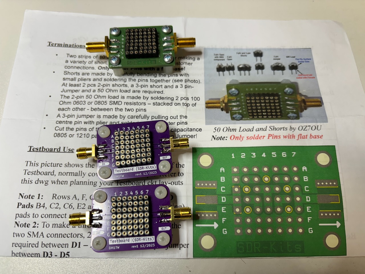
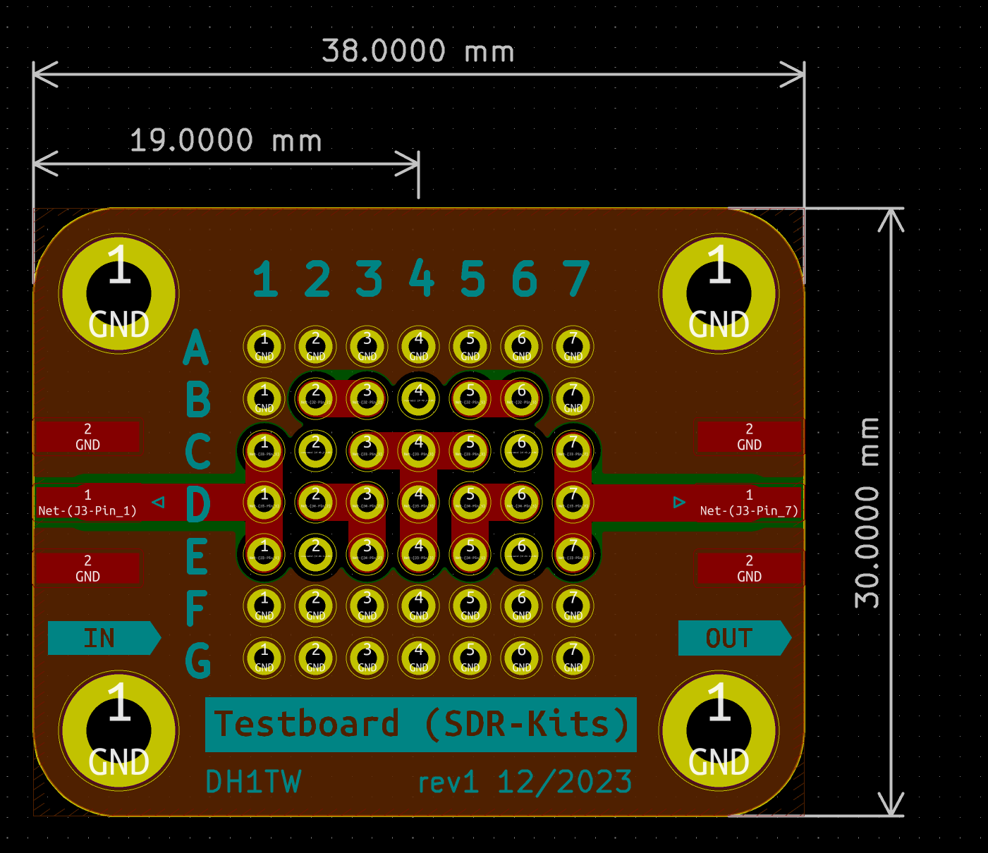
The PCB was designed in KiCad 7. You will most likely have to change / adopt the SMA connectors since I used a couple of non-standard ones which, I just had in stock.
I designed the traces as microstrip lines, matching 50 Ohm. This resulting trace width is 1.85mm using 1,0mm PCB thickness and an Epsilon r = 4.5 of the FR4 material. I get accurate results up to a few hundred Megahertz.
The pin sockets have a 2.54mm spacing.
I use Nylon M3 screws & nuts as feet.
Creative Commons Attribution-ShareAlike 4.0 International
| Qty | Value | Footprint | References |
|---|---|---|---|
| 7 | Conn_01x07_Socket | Pin Header:PinSocket_1x07_P2.54mm_Vertical_SDR-Kits | J1, J2, J3, J4, J5, J6, J7 |
| 4 | MountingHole_Pad | MountingHole:MountingHole_3.2mm_M3_DIN965_Pad | H1, H2, H3, H4 |
| 2 | Conn_Coaxial | Connector_Coaxial:SMA_Aliexpress_EdgeMount | J8, J9 |
| 1 | G*** | kibuzzard-6574F6D7 | kibuzzard-6574F6D7 |
| 1 | G*** | kibuzzard-6574F6F3 | kibuzzard-6574F6F3 |
| 1 | G*** | kibuzzard-6574F576 | kibuzzard-6574F576 |
google/mozc-devices
Circuit diagrams and firmware source code for Gboard DIY keyboards

conorpp/u2f-zero
U2F USB token optimized for physical security, affordability, and style

rusefi/rusefi
rusefi - GPL internal combustion engine control unit

VoronDesign/Voron-Hardware
Cool Hardware designed by the Voron Design group

hoglet67/RGBtoHDMI
Bare-metal Raspberry Pi project that provides pixel-perfect sampling of Retro Computer RGB/YUV video and conversion to HDMI

hackclub/OnBoard
💡 Join 1,000 teenagers and make your first PCB with a $100 grant!


It measures 38 × 30 mm and has 2 copper layers, 1.6 mm thick.
16 parts. The full list of its parts is on this page, with links to each part's symbol and footprint where PCBKit's library has them.
From the dh1tw/vna-testboard repository on GitHub, at the commit this page was made from: the board is sdr-kits-testboard.kicad_pcb and its schematic sdr-kits-testboard.kicad_sch. PCBKit opens the board in the browser, with nothing to install.
Its repository states no licence, so its author keeps all rights: ask dh1tw before reusing the design.