2 layers100 × 100 mm
 dexterlb/led_controller
A simple device for controlling LEDs
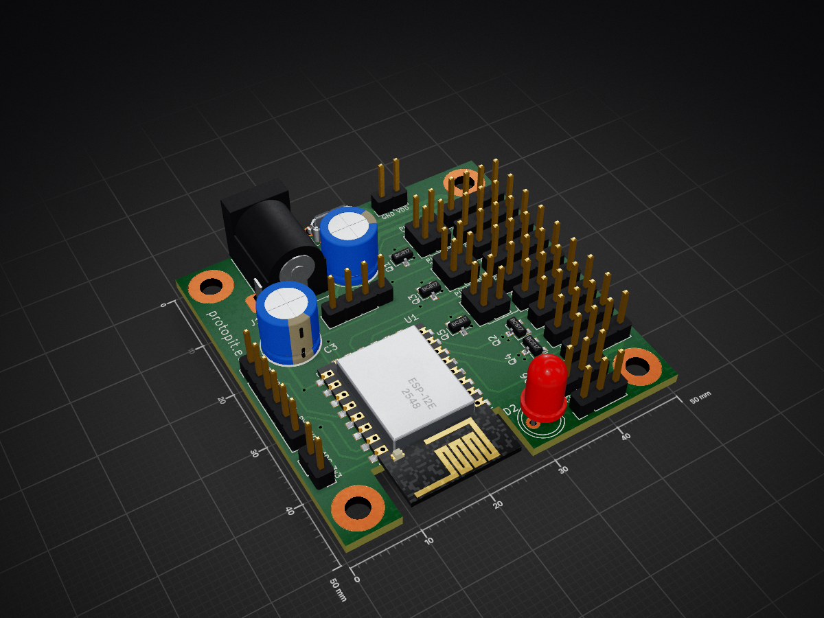
Switcher is an open-source printed circuit board by dexterlb, from the dexterlb/led_controller repository on GitHub. It is a 2-layer board of 50 × 50 mm with 64 parts on 46 nets, routed with 445 tracks and 25 vias.
It is built around the ESP-12E and BC817. Its parts include 27 resistors, 16 connectors, 6 capacitors, 6 transistors and 1 IC. It belongs with the ESP8266 boards of this library.


| Qty | Value | Footprint | References |
|---|---|---|---|
| 13 | 4.7k | Resistor_SMD:R_0805_2012Metric_Pad1.15x1.40mm_HandSolder | R3, R4, R5, R6, R8, R10, R13, R14, R17, R21, R22, R24, R27 |
| 12 | 1k | Resistor_SMD:R_0805_2012Metric_Pad1.15x1.40mm_HandSolder | R7, R9, R11, R12, R15, R16, R18, R19, R20, R23, R25, R26 |
| 6 | BC817 | Package_TO_SOT_SMD:SOT-23 | Q1, Q2, Q3, Q4, Q5, Q6 |
| 4 | O1 | Connector_PinHeader_2.54mm:PinHeader_1x04_P2.54mm_Vertical | J5, J8, J9, J10 |
| 3 | 100n | Capacitor_SMD:C_0805_2012Metric_Pad1.15x1.40mm_HandSolder | C1, C2, C7 |
| 3 | VSEL | Connector_PinHeader_2.54mm:PinHeader_2x02_P2.54mm_Vertical | JP1, JP2, JP3 |
| 2 | 470uF | Capacitor_THT:CP_Radial_D8.0mm_P3.50mm | C3, C8 |
| 2 | POWER_OUT | Connector_PinHeader_2.54mm:PinHeader_1x03_P2.54mm_Vertical | J4, J16 |
| 1 | 10p | Capacitor_SMD:C_0805_2012Metric_Pad1.15x1.40mm_HandSolder | C10 |
| 1 | 150k | Resistor_SMD:R_0805_2012Metric_Pad1.15x1.40mm_HandSolder | R2 |
| 1 | Barrel_Jack_Switch | Connector_BarrelJack:BarrelJack_Horizontal | J14 |
| 1 | DCDC | Connector_PinHeader_2.54mm:PinHeader_1x04_P2.54mm_Vertical | J1 |
| 1 | DEBUG | Connector_PinHeader_2.54mm:PinHeader_1x06_P2.54mm_Vertical | J17 |
| 1 | ESP-12E | RF_Module:ESP-12E | U1 |
| 1 | I1 | Connector_PinHeader_2.54mm:PinHeader_1x04_P2.54mm_Vertical | J11 |
| 1 | I2 | Connector_PinHeader_2.54mm:PinHeader_1x04_P2.54mm_Vertical | J12 |
| 1 | I3 | Connector_PinHeader_2.54mm:PinHeader_1x04_P2.54mm_Vertical | J13 |
| 1 | LDR03 | Connector_PinHeader_2.54mm:PinHeader_1x02_P2.54mm_Vertical | R1 |
| 1 | LED | LED_THT:LED_D5.0mm | D2 |
| 1 | O2 | Connector_PinHeader_2.54mm:PinHeader_1x04_P2.54mm_Vertical | J6 |
| 1 | O3 | Connector_PinHeader_2.54mm:PinHeader_1x04_P2.54mm_Vertical | J7 |
| 1 | Power | Connector_PinHeader_2.54mm:PinHeader_1x02_P2.54mm_Vertical | J3 |
| 1 | USB_B_Micro | connectors:USB_Micro-B_ATTEND | J2 |
The 60 most common of 64 parts.
It measures 50 × 50 mm and has 2 copper layers, 1.6 mm thick.
64 parts, built around the ESP-12E and BC817. The full list of its parts is on this page, with links to each part's symbol and footprint where PCBKit's library has them.
From the dexterlb/led_controller repository on GitHub, at the commit this page was made from: the board is boards/bundled_esp/switcher/switcher.kicad_pcb and its schematic boards/bundled_esp/encoder/encoder.kicad_sch. PCBKit opens the board in the browser, with nothing to install.
Its repository states no licence, so its author keeps all rights: ask dexterlb before reusing the design.


UzixLS/mist1010-board
10x10cm PCB variant of MIST FPGA project for G738/G706 enclosure

AnaviTechnology/anavi-fume-extractor
Open source WiFi development board for a portable fume extractor with 5V USB-powered fan for absorbing smoke.

Abhi90808/ESP8266-WiFi-Dev-Board
Custom ESP8266-based WiFi development board with onboard USB-to-serial, 3.3V regulator, and breadboard-friendly pinout for IoT prototyping


UzixLS/zxuno1010-board
10x10cm PCB variant of ZX-UNO project for G738/G706 enclosure

UtilitechAS/amsreader-firmware
ESP8266 and ESP32 compatible firmware to read, interpret and publish data to MQTT from smart electrical meters, both DLMS and DSMR is supported


skorokithakis/tiny-ESP8266-breakout
A very small and basic ESP8266 breakout board