2 layers40 × 40 mm
Sensor board 1.2
DevVitek2/RODIA-Pathfinder
AI-generated visualisation of the PCB2.3 board: front (left) and back (right).
14 parts

 DevVitek2/RODIA-Pathfinder
AI-generated visualisation of the PCB2.3 board: front (left) and back (right).
PCB2.3 JF is an open-source printed circuit board by DevVitek2, from the DevVitek2/RODIA-Pathfinder repository on GitHub. It is a 2-layer board of 40 × 40 mm with 71 parts on 72 nets, routed with 424 tracks and 110 vias.
It is built around the RP2040, BMP388 and W25Q128JVSIQ, with the AO3400A among its other parts. Its parts include 25 capacitors, 22 resistors, 5 diodes, 5 connectors and 4 ICs. It belongs with the RP2040 boards of this library.


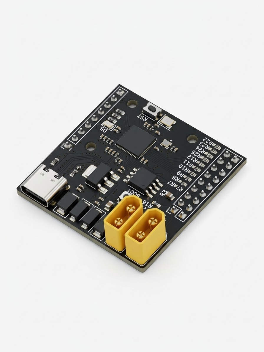
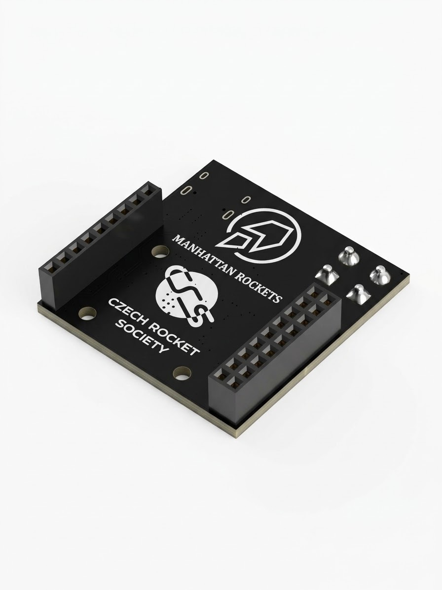
AI-generated visualisation of the PCB2.3 board: front (left) and back (right).
RODIA Pathfinder is the first iteration of a custom RP2040 flight computer for Trinity, the hybrid rocket-drone vehicle of the student team Manhattan Rockets (Czech Rocket Society). It is a 40 × 40 mm, two-layer board designed in KiCad and manufactured and assembled by JLCPCB.
Pathfinder is not meant to fly. It exists to prove the core of the design in hardware (MCU, power, flash, barometer, pyro channel) before the more demanding RODIA (Rocket Onboard Drone Interface Avionics) board is built.
Full documentation (Czech, 19 pages): MR_PCB2_DOCUM_FINAL.pdf
| Parameter | Value |
|---|---|
| MCU | RP2040 (dual Cortex-M0+, no FPU) |
| Flash | W25Q128JVS, 16 MB, QSPI (firmware + sensor data) |
| Sensor | BMP388 barometer (I2C, address 0x76) |
| Power | USB-C (5 V) or Li-Po 2S–3S via XT30, Schottky OR-ing + TVS protection on both inputs |
| Logic | 3.3 V, NCP1117-3.3 linear regulator |
| Pyro channel | AO3400A MOSFET, powered directly from the battery, XT30 output (J5) |
| Size | 40 × 40 mm, 1.6 mm, 2 layers, 3 × 2.5 mm mounting holes |
| Expansion | J3 (2 × 9) and J4 (1 × 9) pin headers, 2.54 mm, for stacking boards |
| 3D view, top | 3D view, bottom |
|---|---|
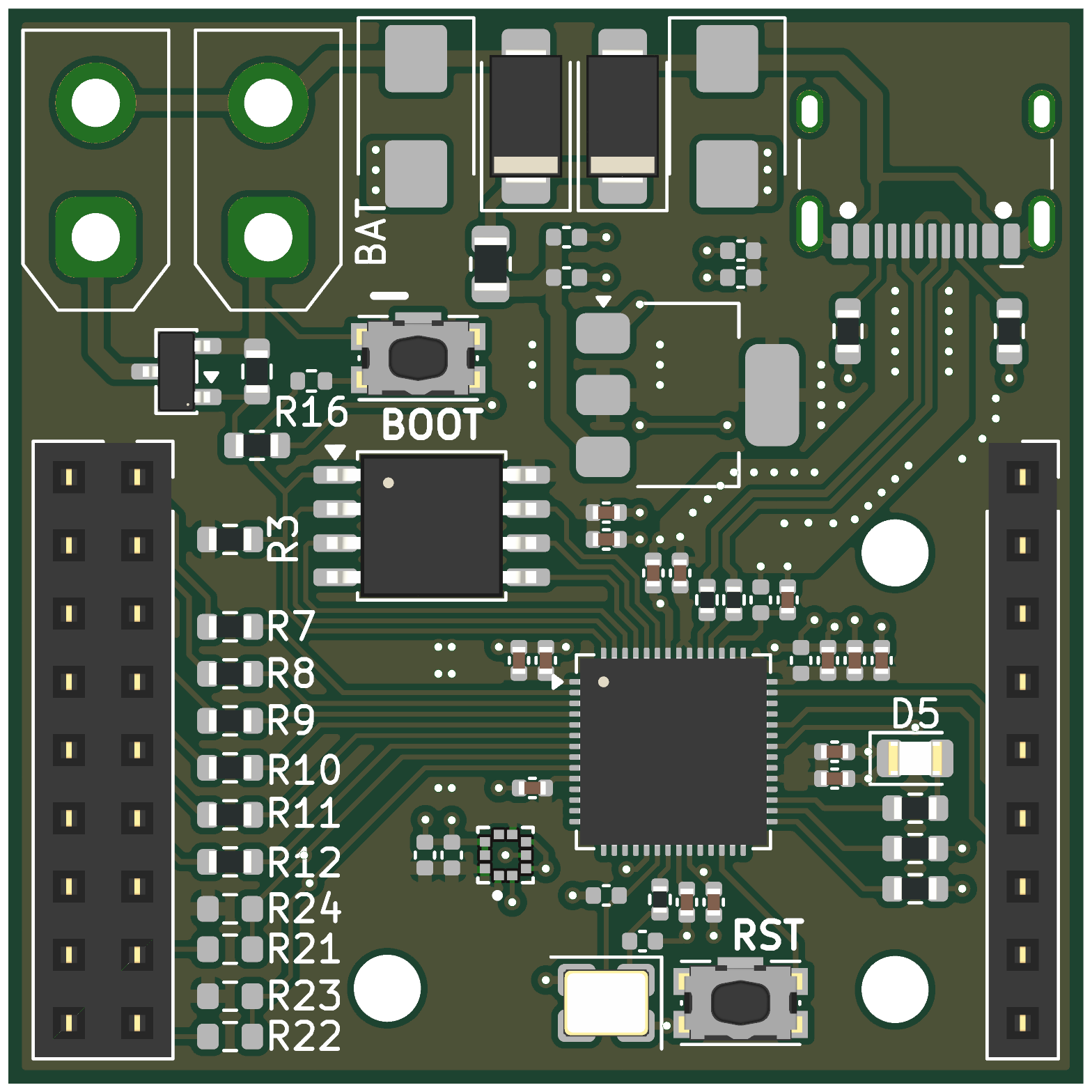 | 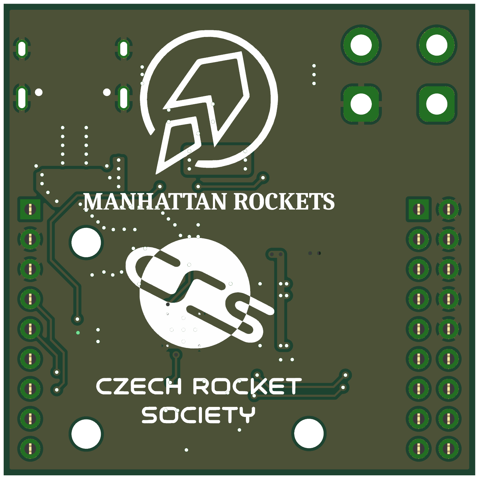 |
Full schematic: images/schematic.pdf
Verified on hardware
Known issues (input for the next revision)
rodia-pathfinder/AVIONICS.md).
├── README.md
├── MR_PCB2_DOCUM_FINAL.pdf full Pathfinder documentation (Czech)
├── images/ renders, schematic blocks, copper layers
├── rodia-pathfinder/ design files
│ ├── AVIONICS.md pin map, SPI rules, firmware build, hardware status
│ ├── PCB2.3_JF/ main board: KiCad project + JLCPCB production files
│ ├── Sensor_board_1.2/ extension board: BNO085, SD card, LEDs, buzzer
│ └── datasheets+components+min-design/ datasheets, component lists, RP2040 minimal reference design
└── rodia/ the next board
├── RODIA_project_brief_EN.pdf motivation, idea, requirements
└── RODIA_block_diagram.pdf / .odg simplified system diagramTrinity flies a ballistic rocket ascent followed by a powered, controlled drone descent.
The drone flight controller handles the descent, but its firmware only provides filtered data
tuned for propeller flight, and its accelerometer is close to its range limit under rocket loads.
RODIA is a second, independent flight computer that connects to the drone flight controller,
follows drone-FC mechanical standards, logs raw sensor data, talks to the ground station
and can carry out the critical functions (parachute deployment) on its own if the drone FC
fails. See rodia/RODIA_project_brief_EN.pdf.
Designed by Vít Krejčí (avionics, Manhattan Rockets, a student rocketry team operating under the Czech Rocket Society).
Datasheets in rodia-pathfinder/datasheets+components+min-design/ belong to their respective
manufacturers and are included for reference only.
| Qty | Value | Footprint | References |
|---|---|---|---|
| 14 | 100n | Capacitor_SMD:C_0402_1005Metric | C5, C6, C8, C10, C11, C12, C13, C14, C15, C16, C17, C21, C30, C31 |
| 11 | 220 | Resistor_SMD:R_0603_1608Metric | R7, R8, R9, R10, R11, R12, R13, R14, R15, R21, R22 |
| 7 | 10u | Capacitor_SMD:C_0402_1005Metric | C3, C4, C9, C18, C19, C20, C22 |
| 2 | 15p | Capacitor_SMD:C_0402_1005Metric | C1, C2 |
| 2 | 1k | Resistor_SMD:R_0402_1005Metric | R4, R16 |
| 2 | 1u | Capacitor_SMD:C_0402_1005Metric | C28, C29 |
| 2 | 4.7k | Resistor_SMD:R_0603_1608Metric | R23, R24 |
| 2 | 5k1 | Resistor_SMD:R_0603_1608Metric | R5, R6 |
| 2 | D | Diode_SMD:D_SMB | D1, D4 |
| 2 | D_Schottky | Diode_SMD:D_SMA | D2, D3 |
| 1 | 100k | Resistor_SMD:R_0603_1608Metric | R17 |
| 1 | 27 | Resistor_SMD:R_0402_1005Metric | R1 |
| 1 | 27R | Resistor_SMD:R_0402_1005Metric | R2 |
| 1 | 47R | Resistor_SMD:R_0603_1608Metric | R18 |
| 1 | AO3400A | Package_TO_SOT_SMD:SOT-23 | Q1 |
| 1 | BAT | Connector_AMASS:AMASS_XT30UPB-M_1x02_P5.0mm_Vertical | J2 |
| 1 | BMP388 | BMP388:PQFN50P200X200X80-10N | U6 |
| 1 | BOOT | Button_Switch_SMD:SW_Push_1P1T-SH_NO_CK_KMR2xxG | SW1 |
| 1 | Conn_01x09 | Connector_PinSocket_2.54mm:PinSocket_1x09_P2.54mm_Vertical | J4 |
| 1 | Conn_02x09_Odd_Even | Connector_PinSocket_2.54mm:PinSocket_2x09_P2.54mm_Vertical | J3 |
| 1 | Crystal_GND24 | Crystal:Crystal_SMD_3225-4Pin_3.2x2.5mm | Y1 |
| 1 | DNF | Resistor_SMD:R_0603_1608Metric | R3 |
| 1 | FerriteBead_Small | Resistor_SMD:R_0805_2012Metric | FB1 |
| 1 | LED | LED_SMD:LED_0805_2012Metric | D5 |
| 1 | LOGO | graphics7:trylogo_MR4 | G*** |
| 1 | LOGO | trylogo:pcbcrslogo | G*** |
| 1 | NCP1117-3.3_SOT223 | Package_TO_SOT_SMD:SOT-223-3_TabPin2 | U2 |
| 1 | RP2040 | Package_DFN_QFN:QFN-56-1EP_7x7mm_P0.4mm_EP3.2x3.2mm_ThermalVias | U1 |
| 1 | RST | Button_Switch_SMD:SW_Push_1P1T-SH_NO_CK_KMR2xxG | SW2 |
| 1 | USB_C_Receptacle_USB2.0_16P | Connector_USB:USB_C_Receptacle_HCTL_HC-TYPE-C-16P-01A | J1 |
| 1 | W25Q128JVS | Package_SO:SOIC-8_5.3x5.3mm_P1.27mm | U3 |
| 1 | palnik | Connector_AMASS:AMASS_XT30UPB-M_1x02_P5.0mm_Vertical | J5 |
The 68 most common of 71 parts.
It measures 40 × 40 mm and has 2 copper layers, 1.6 mm thick.
71 parts, built around the RP2040, BMP388, W25Q128JVSIQ and AO3400A. The full list of its parts is on this page, with links to each part's symbol and footprint where PCBKit's library has them.
From the DevVitek2/RODIA-Pathfinder repository on GitHub, at the commit this page was made from: the board is rodia-pathfinder/PCB2.3_JF/Test.kicad_pcb and its schematic rodia-pathfinder/PCB2.3_JF/Test.kicad_sch. PCBKit opens the board in the browser, with nothing to install.
Its repository states no licence, so its author keeps all rights: ask DevVitek2 before reusing the design.
DevVitek2/RODIA-Pathfinder
AI-generated visualisation of the PCB2.3 board: front (left) and back (right).


matveylapin/CopterCat_cm4
Полётный контроллер для стандарта FMU-v6u. Обычно на дронах для программирования устанавливают полётный контроллер, одноплатный компьютер и иногда arduino.

ishantmahatopro/Vayu-F722
Custom 42x42mm 4-layer STM32F722 FPV flight controller for 5in and 7in cinematic and telemetry quads.

WilmervH/pyramid-of-brightness
This was supposed to be a pyramid (or more of a triagle) but I thought I'd be too difficult to arrange the pixels in a neat way. So I made it a square. The name stuck.


