Fall Detection and Alerting System
"Fall seven times, stand up eight." - Japanese Proverb
While the proverb speaks of resilience, falls can be a critical health concern, especially for the elderly. This project presents a robust fall detection system that combines wearable technology and machine learning to provide timely alerts, mitigating the risks associated with delayed assistance.
This system is built upon the research detailed in the paper "Fall Detection System for Elderly People Using LSTM", Alternate Link. (Link to full paper — https://www.nepjol.info/index.php/joeis/article/view/93497 or https://www.researchgate.net/publication/404278061_Fall_Detection_System_for_Elderly_People_Using_LSTM) It leverages a custom-designed wearable device to monitor user movement and a sophisticated deep learning model to accurately distinguish between normal daily activities and dangerous falls.
The system is architecturally divided into two main sub-systems:
- Wearable Detector: A compact, body-worn device that captures real-time motion data.
- System Groundstation: A stationary unit that receives alerts from the wearable and triggers local alarms.
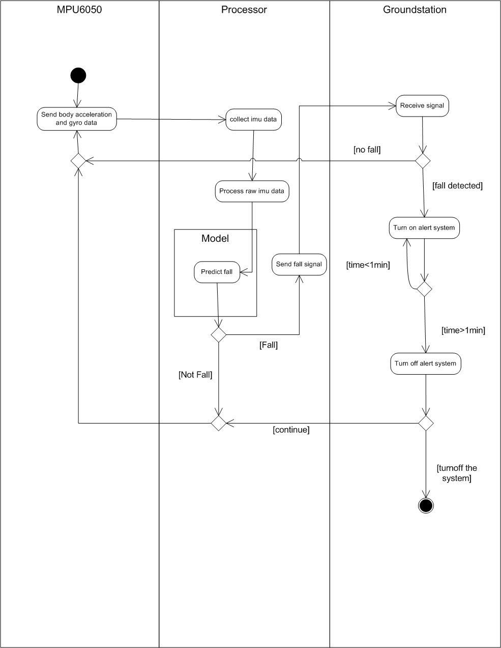
System Activity Diagram
The operational flow of the system is as follows:
Wearable Detector
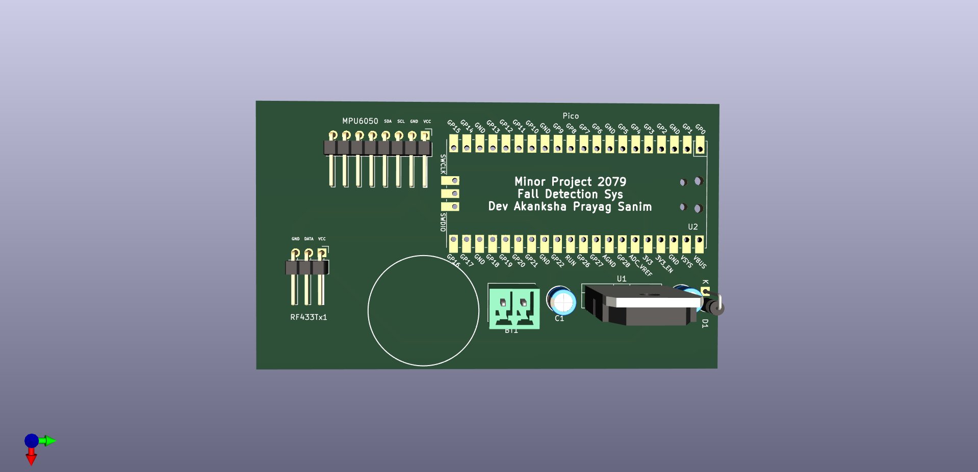
This is the core data acquisition and processing unit of the system. It is designed to be worn on the user's shoulder—a location chosen to minimize motion impedance and ensure stable, accurate readings. The device continuously captures motion data, processes it with an onboard machine learning model, and transmits an alert if a fall is detected.
Key Components:
- Microcontroller: Raspberry Pi Pico (RP2040)
- Sensor: MPU-6050, a 6-axis Inertial Measurement Unit (IMU) that provides accelerometer and gyroscope data.
- Wireless Communication: The hardware is designed with a dedicated slot for an HC-05 Bluetooth module to transmit alerts wirelessly to the groundstation.
- Power Supply: The device can be powered via a DC source (regulated by an LM7805 IC) or a direct USB connection.
Machine Learning Model
The intelligence of the system lies in its fall detection model. Instead of simple thresholds, this project employs a Long Short-Term Memory (LSTM) neural network, a type of recurrent neural network (RNN) ideal for analyzing sequential data like human motion.
- Model Architecture: The final system uses a refined double-layer LSTM model. This architecture proved significantly more effective than an initial single-layer model, demonstrating a superior ability to learn the complex temporal patterns that differentiate a fall from other activities.
- Data Collection: The model was trained on a dataset created by capturing sequential motion data from participants mimicking the daily activities of the elderly (walking, sitting, standing) as well as simulated fall events.
- Performance: The double-layer LSTM model achieved an impressive accuracy of 97.8%. More critically, it demonstrated high sensitivity in identifying falls, reducing the dangerous instances of false negatives that plagued simpler models.
| Metric | 1-Layer LSTM Model | 2-Layer LSTM Model |
|---|
| Accuracy | 92.19% | 97.8% |
| Sensitivity (Recall) | 38.37% | 91.86% |
| Precision | 75.00% | 87.78% |
| F1-Score | 50.77% | 89.77% |
The trained model is deployed directly onto the Raspberry Pi Pico, allowing for real-time, on-device inference without reliance on a constant internet connection.
PCB Design
System Groundstation
The groundstation acts as the central alerting hub. It remains in a fixed location within the user's home, listening for signals from the wearable device. Upon receiving a fall alert, it triggers both audible and visual alarms to notify nearby caregivers.
Key Components:
- Microcontroller: Atmega328p
- Wireless Communication: An RF/Bluetooth receiver to communicate with the wearable device.
- Alerting Peripherals: A loud buzzer and bright LEDs.
- Power Supply: 5V DC power, supplied by the custom rectifier circuit below.
Power Supply Rectifier
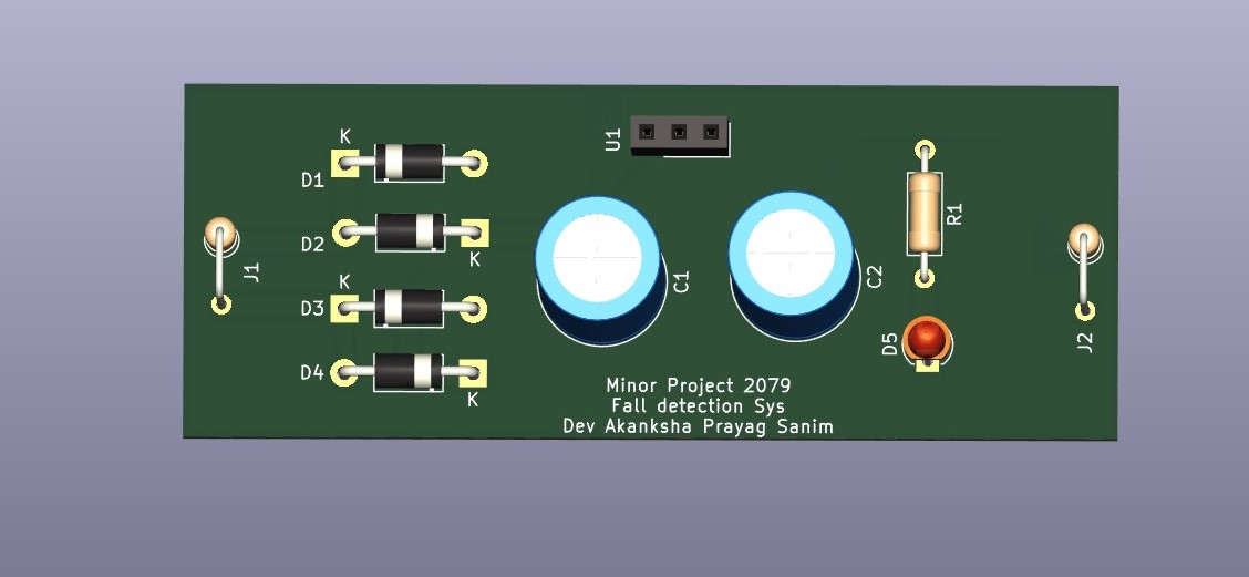
This custom circuit was designed to provide a stable, regulated 5V DC supply for the groundstation from an AC source.
Components:
- Bridge Rectifier (Diodes)
- LM7805 Voltage Regulator
- Smoothing Capacitors
- Resistor
PCB Design
Authors
- Sanim Kumar Khatri - GitHub
- Devraj Parajuli - GitHub
- Bhupendra Chaulagain- Github
- Prayag Man Mane - Github
- Sandesh Thapa - Github
IOE, Pulchowk Campus
License
This project is released for academic and research purposes. Hardware designs and firmware are provided as-is.


