2 layers61 × 61 mm
 devcristi/smartwatch
This project is a bare-metal implementation of a smartwatch using an AVR microcontroller (ATmega2560). The smartwatch is designed to operate at a low level, utilizing direct register manipulation and avoiding high-level…
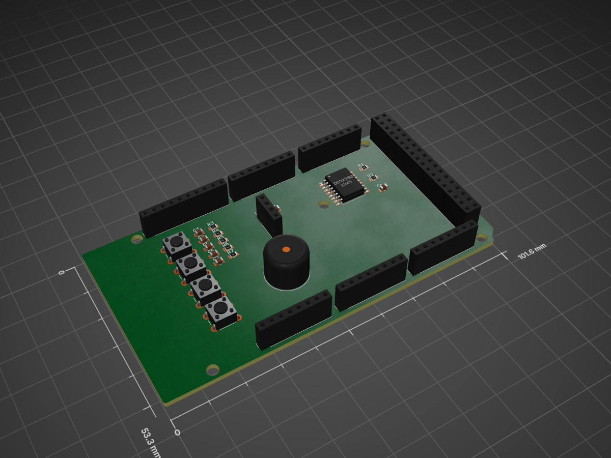
Mega shield is an open-source printed circuit board by devcristi, from the devcristi/smartwatch repository on GitHub. It is a 2-layer board of 101.6 × 53.3 mm with 34 parts on 87 nets.
It is built around the BME280 and DS3231MZ+. Its parts include 7 capacitors, 7 resistors, 7 connectors, 4 switches and 2 ICs.


This project is a bare-metal implementation of a smartwatch using an AVR microcontroller (ATmega2560). The smartwatch is designed to operate at a low level, utilizing direct register manipulation and avoiding high-level abstractions. The entire project is written in C with modular architecture.This project is a bare-metal implementation of a smartwatch using the STM-32 Nucleo development board. The smartwatch is designed to operate at a low level, utilizing direct register manipulation and avoiding high-level abstractions. The project is written entirely in C.
Real-Time Clock (RTC): DS3231 module for precise timekeeping with I2C interface- Real-Time Clock (RTC): DS3231 module for precise timekeeping.
LCD Display: GC9A01 compatible 16x2 LCD via I2C- Motion Sensing: MPU6050 sensor for accelerometer and gyroscope data.
Menu Navigation: 3-mode menu system (Time, Temperature, Stopwatch)- Heart Rate and SpO2 Monitoring: MAX30102 sensor for health monitoring.
Stopwatch Functionality: Start/Pause and Reset operations with centisecond precision- Environmental Sensing: BME280 sensor for temperature, humidity, and pressure measurements.
Temperature Monitoring: Real-time temperature reading from DS3231 sensor- Battery Management: TP4056 module for battery charging and monitoring.
Button Control: Three interrupt-driven buttons for navigation and control- Display: GC9A01 round LCD for user interface.
Timer-Based Scheduling: TIMER1 for precise timing and interrupt handling
ATmega2560 Microcontroller: Core processor- Direct Register Access: All peripherals are controlled through direct register manipulation, ensuring maximum control and efficiency.
DS3231 RTC Module: Real-time clock and temperature sensor (I2C @ 0x68)- Low-Level Drivers: Custom drivers are developed for each module to interface with the STM-32 microcontroller.
LCD 16x2 Module: Display with I2C backpack (I2C @ 0x27)
Push Buttons: ## Hardware Components
Button NEXT (PE4, INT4): Navigate menu forward1. STM-32 Nucleo Board: The core microcontroller platform.
Button PREV (PE5, INT5): Navigate menu backward 2. DS3231 RTC Module: Provides accurate timekeeping.
Button ACTION (PD2, INT2): Start/Pause/Reset stopwatch3. MPU6050 Sensor: Measures motion and orientation.
MAX30102 Sensor: Monitors heart rate and SpO2 levels.
smartwatch/7. **GC9A01 LCD**: Displays smartwatch data and user interface.

├── Core/

│   ├── Inc/                    # Header files## Goals

│   │   ├── main.h              # Main application header- Develop a fully functional smartwatch with essential features.

│   │   ├── i2c.h               # I2C/TWI interface- Implement all functionalities using bare-metal programming techniques.

│   │   ├── buttons.h           # Button handling- Optimize performance and power consumption through efficient low-level coding.

│   │   ├── timer.h             # Timer interrupt handling

│   │   └── stopwatch.h         # Stopwatch interface## Future Enhancements

│   └── Src/                    # Source files- Add additional sensors or modules for extended functionality.

│       ├── main.c              # Main application logic- Implement power-saving modes to extend battery life.

│       ├── i2c.c               # I2C driver implementation- Enhance the user interface with advanced graphics.

│       ├── buttons.c           # Button ISR and handling
avr-gcc -mmcu=atmega2560 -DF_CPU=16000000UL -O2 \
  Core/Src/*.c Drivers/Custom/Src/*.c \
  -o smartwatch.elf

avr-objcopy -O ihex smartwatch.elf smartwatch.hexavrdude -p m2560 -c stk500v2 -P COM3 -b 115200 -U flash:w:smartwatch.hex:i| Function | Pin | AVR Port | Interrupt |
|---|---|---|---|
| Button NEXT | PE4 | PORTE4 | INT4 |
| Button PREV | PE5 | PORTE5 | INT5 |
| Button ACTION | PD2 | PORTD2 | INT2 |
| I2C SDA | PD1 | PORTD1 | - |
| I2C SCL | PD0 | PORTD0 | - |
This project is open-source and available under the MIT License.
devcristi - Embedded Systems Development
| Qty | Value | Footprint | References |
|---|---|---|---|
| 7 | 100nF | Capacitor_SMD:C_0805_2012Metric | C1, C2, C3, C4, C5, C6, C7 |
| 6 | MountingHole_3.2mm | Arduino_MountingHole:MountingHole_3.2mm | MH1, MH2, MH3, MH4, MH5, MH6 |
| 4 | 10k | Resistor_SMD:R_0805_2012Metric | R3, R4, R5, R6 |
| 2 | 4.7k | Resistor_SMD:R_0805_2012Metric | R1, R2 |
| 2 | Analog | Connector_PinSocket_2.54mm:PinSocket_1x08_P2.54mm_Vertical | J3, J5 |
| 1 | 100 | Resistor_SMD:R_0805_2012Metric | R7 |
| 1 | BME280 | Connector_PinSocket_2.54mm:PinSocket_1x04_P2.54mm_Vertical | U2 |
| 1 | BTN_BACK | Button_Switch_THT:SW_PUSH_6mm | SW4 |
| 1 | BTN_DOWN | Button_Switch_THT:SW_PUSH_6mm | SW2 |
| 1 | BTN_SELECT | Button_Switch_THT:SW_PUSH_6mm | SW3 |
| 1 | BTN_UP | Button_Switch_THT:SW_PUSH_6mm | SW1 |
| 1 | Buzzer | Buzzer_Beeper:Buzzer_12x9.5RM7.6 | BZ1 |
| 1 | Communication | Connector_PinSocket_2.54mm:PinSocket_1x08_P2.54mm_Vertical | J6 |
| 1 | DS3231M | Package_SO:SOIC-16W_7.5x10.3mm_P1.27mm | U1 |
| 1 | Digital | Connector_PinSocket_2.54mm:PinSocket_2x18_P2.54mm_Vertical | J7 |
| 1 | PWM | Connector_PinSocket_2.54mm:PinSocket_1x08_P2.54mm_Vertical | J4 |
| 1 | PWM | Connector_PinSocket_2.54mm:PinSocket_1x10_P2.54mm_Vertical | J2 |
| 1 | Power | Connector_PinSocket_2.54mm:PinSocket_1x08_P2.54mm_Vertical | J1 |
It measures 101.6 × 53.3 mm and has 2 copper layers, 1.6 mm thick.
34 parts, built around the BME280 and DS3231MZ+. The full list of its parts is on this page, with links to each part's symbol and footprint where PCBKit's library has them.
From the devcristi/smartwatch repository on GitHub, at the commit this page was made from: the board is mega_shield/mega_shield.kicad_pcb and its schematic mega_shield.kicad_sch. PCBKit opens the board in the browser, with nothing to install.
Its repository states no licence, so its author keeps all rights: ask devcristi before reusing the design.

Kalash4152/smart-dustbin-round-two
Designed and simulated a Smart Dustbin & Smart Traffic Lights system using Arduino, ESP32, and sensors at DJSCE Unplugged 2.0.

haum2002/EWP-Control
SmartCoolingv2.1 menggabungkan firmware SmartCooling dengan reka bentuk EWP Controller ini. RP2350B kekal sebagai pengawal keselamatan dan actuator kritikal, manakala ESP32-S3 mengurus UI, Wi-Fi, BLE, diagnostik dan…

lalithk06/PCB_Designs
This repository contains various PCB design projects made using KiCad

Lelk0e/DA_Sensorbox
Diplomarbeit 2024-2025 mit der Firma B2 electronics. Das Ziel ist es eine Sensorbox mit dem ESP32, als Basis zu entwickeln. Diese Sensorbox soll über ein Mesh-Netzwerk erweiterbar werden.

Mateuszworo97/Projects
Apiary Water Dispensing System — This is a device design whose purpose is to automatically supply bee water from an underground tank. In hard-to-reach places and with limited access to fresh water.

OlegDemk/stm32F401CCU_NTF24L01_RX_TX_Sleep
The project base on STM32F401CCU microcontroller and NRF24L01 radio module. Project was create on STM32 Cube IDE.

PriyaUdhayakumar/ESP32-Environmental-Monitoring-Data-Logger
ESP32-based environmental monitoring data logger using BME280, DS3231 RTC, microSD card, ESP-IDF and FreeRTOS.