2 layers121.8 × 78.3 mm
 devan0404/Pcb-Design
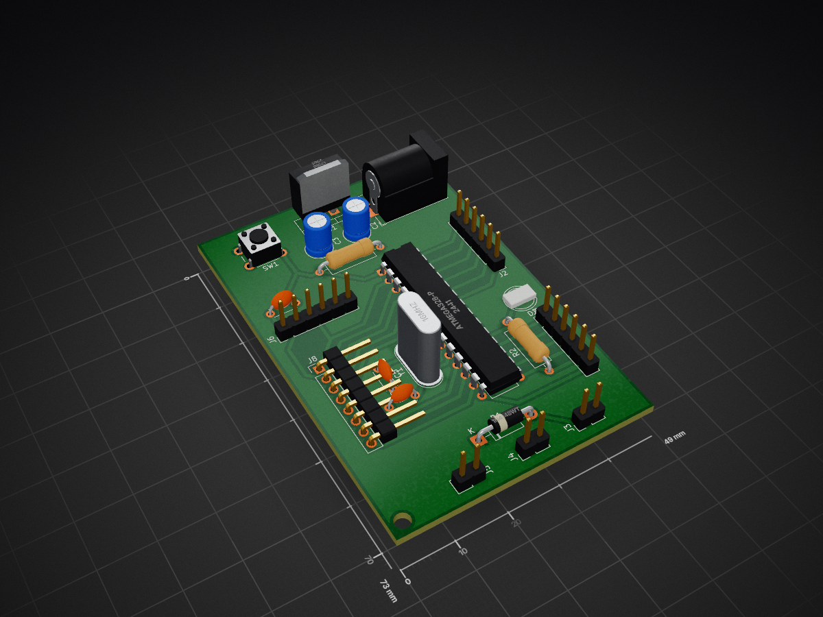
Atmega is an open-source printed circuit board by devan0404, from the devan0404/Pcb-Design repository on GitHub. It is a 2-layer board of 49 × 73 mm with 21 parts on 32 nets, routed with 121 tracks and 0 vias.
It is built around the ATMEGA328-PU, L7805 and 1N4148WT. Its parts include 8 connectors, 5 capacitors, 2 resistors, 2 ICs and 2 diodes. It belongs with the AVR (ATmega, ATtiny) boards of this library.


| Qty | Value | Footprint | References |
|---|---|---|---|
| 2 | 10u | Capacitor_THT:C_Radial_D5.0mm_H7.0mm_P2.00mm | C2, C3 |
| 2 | 22p | Capacitor_THT:C_Disc_D4.3mm_W1.9mm_P5.00mm | C4, C5 |
| 2 | Conn_01x06_Pin | Connector_PinHeader_2.54mm:PinHeader_1x06_P2.54mm_Vertical | J2, J7 |
| 2 | Power | Connector_PinHeader_2.54mm:PinHeader_1x02_P2.54mm_Vertical | J4, J5 |
| 1 | 100n | Capacitor_THT:C_Disc_D4.3mm_W1.9mm_P5.00mm | C1 |
| 1 | 10k | Resistor_THT:R_Axial_DIN0309_L9.0mm_D3.2mm_P12.70mm_Horizontal | R1 |
| 1 | 16Mhz | Crystal:Crystal_HC49-4H_Vertical | Y1 |
| 1 | 1N4148WT | Diode_THT:D_DO-41_SOD81_P10.16mm_Horizontal | D1 |
| 1 | 1k | Resistor_THT:R_Axial_DIN0309_L9.0mm_D3.2mm_P12.70mm_Horizontal | R2 |
| 1 | ATmega328-P | Package_DIP:DIP-28_W7.62mm | U2 |
| 1 | Barrel_Jack_Switch | Connector_BarrelJack:BarrelJack_Horizontal | J1 |
| 1 | Conn_01x08_Pin | Connector_PinHeader_2.54mm:PinHeader_1x08_P2.54mm_Vertical | J8 |
| 1 | L7805 | Package_TO_SOT_THT:TO-220-3_Vertical | U1 |
| 1 | LED | LED_THT:LED_D5.0mm | D2 |
| 1 | Power_BP | Connector_PinHeader_2.54mm:PinHeader_1x02_P2.54mm_Vertical | J3 |
| 1 | RST | Button_Switch_THT:SW_PUSH_6mm | SW1 |
| 1 | USB to TTL | Connector_PinHeader_2.54mm:PinHeader_1x06_P2.54mm_Vertical | J6 |
It measures 49 × 73 mm and has 2 copper layers, 1.6 mm thick.
21 parts, built around the ATMEGA328-PU, L7805 and 1N4148WT. The full list of its parts is on this page, with links to each part's symbol and footprint where PCBKit's library has them.
From the devan0404/Pcb-Design repository on GitHub, at the commit this page was made from: the board is atmega.kicad_pcb and its schematic atmega.kicad_sch. PCBKit opens the board in the browser, with nothing to install.
Its repository states no licence, so its author keeps all rights: ask devan0404 before reusing the design.

syeedameen/miniflight
Budget Flight Controller for Drones with ATmega328P Microcontroller

BaselMohamed802/EyeTalk
An Accessible AAC Device Using Visual Speech to empower and help disabled people talk and communicate, as a graduation project for my

Shreyas-k-p/Auto-SMPS
An Arduino-based system that monitors two SMPS units and automatically switches to a backup if the main supply fails.

Esdras2/dspic30f-devboard-kit
Breadboard-friendly dsPIC30F4011 (DIP-40, all-THT) dev board—KiCad 8 hardware (Rev D) plus XC16 demo firmware, 12 V→5 V regulation, crystal clock & ICSP.

guptapurnima/Digital-Electronics-Design-Digital-Frequency-Meter-
Designed Schmitt Trigger and CMOS logic circuits using CD4007 and CD4026 ICs. Created complete schematics, PCB footprints, and 3D models in KiCAD. Validated signal integrity across the designed circuits.


peterheinrich/InternetOverSpaghetti
Transmitting IP packages over a pair of spaghetti thus demonstrating how media independent IP really is.