
2 layers60 × 40 mm
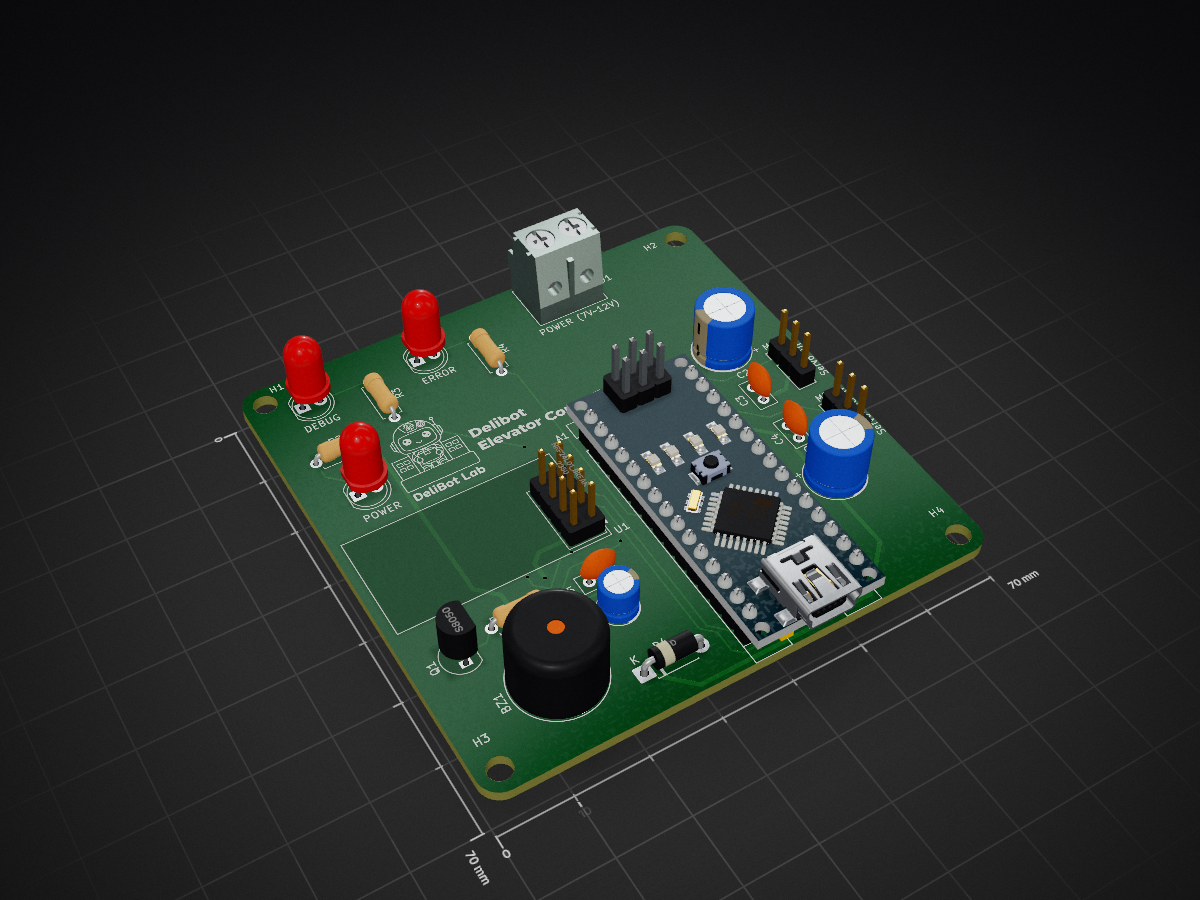
 Delibot-Lab/Elevator-Controller-PCB
PCB to controller elevator using 2 servo & radio transmission!
ElevatorController is an open-source printed circuit board by Delibot-Lab, from the Delibot-Lab/Elevator-Controller-PCB repository on GitHub, published under the Apache-2.0 licence. It is a 2-layer board of 70 × 70 mm with 26 parts on 35 nets, routed with 136 tracks and 6 vias.
It is built around the S8050. Its parts include 6 capacitors, 4 resistors, 4 diodes, 1 IC and 1 transistor. It belongs with the robots and motor control and radio and wireless boards and the AVR (ATmega, ATtiny) boards of this library.
A KiCad PCB that drives a small elevator model using two servo motors, controlled wirelessly over an NRF24L01 radio link.
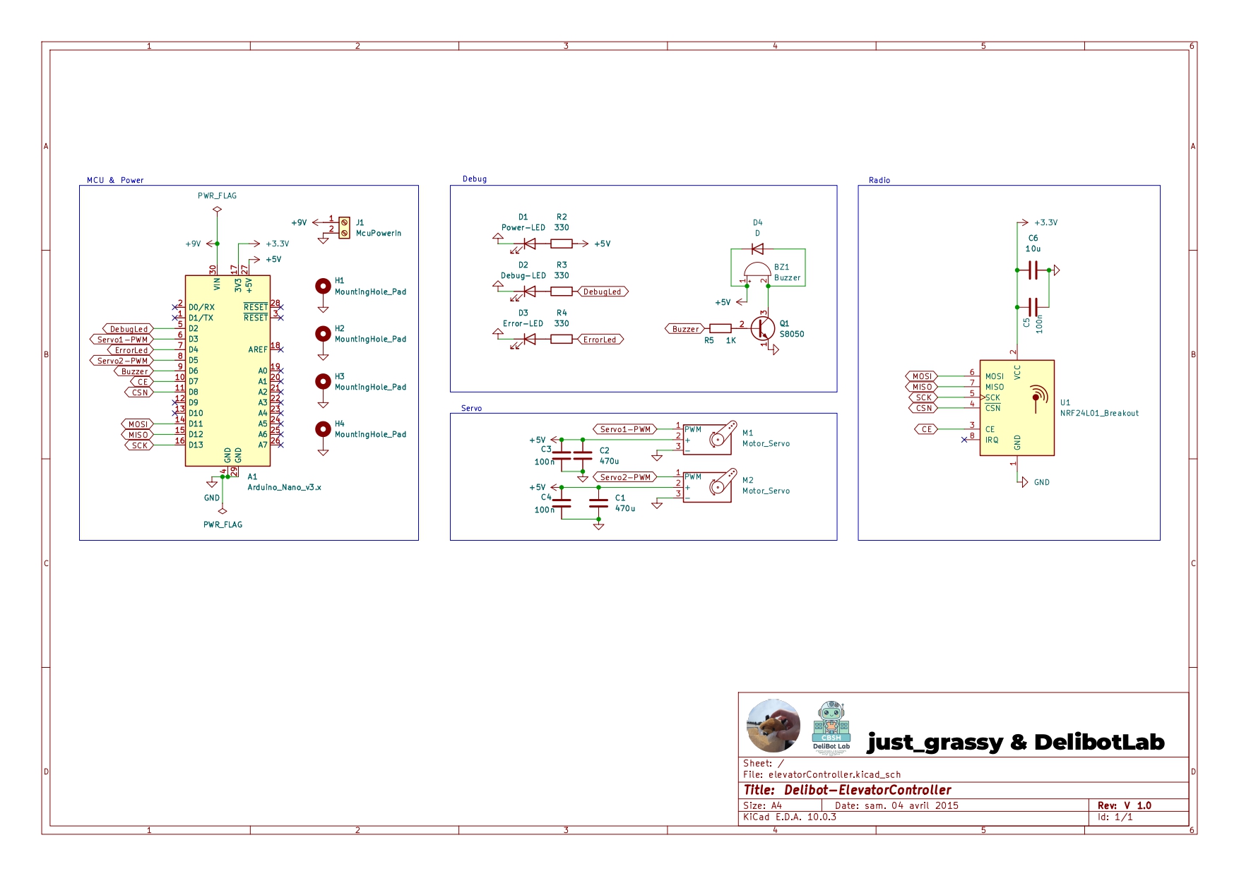
The board is built around an Arduino Nano that:
| Ref | Part | Description |
|---|---|---|
| A1 | Arduino Nano v3.x | Main controller |
| U1 | NRF24L01 Breakout | 2.4GHz radio transceiver |
| M1, M2 | Servo motors | Elevator actuation (3-pin headers) |
| BZ1 | Buzzer | Audible feedback |
| D1 | LED | Power indicator |
| D2 | LED | Debug indicator |
| D3 | LED | Error indicator |
| D4 | Diode | Protection |
| Q1 | S8050 NPN transistor | Switching |
| J1 | Terminal block (2-pin) | MCU power input |
| R2–R5 | Resistors (330Ω x3, 1kΩ) | LED/transistor biasing |
| C1, C2 | 470µF electrolytic | Power supply filtering |
| C3–C5 | 100nF ceramic | Decoupling |
| C6 | 10µF electrolytic | Filtering |
Full BOM: jlcpcb/elevatorController.csv
elevatorController/   KiCad project (schematic, PCB layout, Gerbers, DRC report)
jlcpcb/                JLCPCB-ready fabrication output (Gerbers, drill files, BOM)
exports/               Rendered board images and PDF schematic/layout export
libraries/ Custom KiCad symbol/footprint/3D-model libraries (NRF24L01 module)elevatorController/elevatorController.kicad_pro.libraries/. If symbols/footprints are missing, add libraries/ to your KiCad library table — see libraries/NRF24L01_/how-to-import.htm for instructions.Ready-to-order Gerbers, drill files, and BOM for JLCPCB are in jlcpcb/ (also bundled as jlcpcb/gerber.zip). The board is 2-layer and passes DRC with 0 violations (see elevatorController/DRC.rpt).
Apache License 2.0 — see LICENSE.
| Qty | Value | Footprint | References |
|---|---|---|---|
| 4 | MountingHole_Pad | Arduino_MountingHole:MountingHole_3.2mm | H1, H2, H3, H4 |
| 3 | 100n | Capacitor_THT:C_Disc_D5.0mm_W2.5mm_P2.50mm | C3, C4, C5 |
| 3 | 330 | Resistor_THT:R_Axial_DIN0207_L6.3mm_D2.5mm_P7.62mm_Horizontal | R2, R3, R4 |
| 2 | 470u | Capacitor_THT:CP_Radial_D8.0mm_P3.50mm | C1, C2 |
| 2 | Motor_Servo | Connector_PinHeader_2.54mm:PinHeader_1x03_P2.54mm_Vertical | M1, M2 |
| 1 | 10u | Capacitor_THT:CP_Radial_D5.0mm_P2.00mm | C6 |
| 1 | 1K | Resistor_THT:R_Axial_DIN0207_L6.3mm_D2.5mm_P7.62mm_Horizontal | R5 |
| 1 | Arduino_Nano_v3.x | Module:Arduino_Nano | A1 |
| 1 | Buzzer | Buzzer_Beeper:Buzzer_12x9.5RM7.6 | BZ1 |
| 1 | D | Diode_THT:D_DO-41_SOD81_P7.62mm_Horizontal | D4 |
| 1 | Debug-LED | LED_THT:LED_D5.0mm | D2 |
| 1 | Error-LED | LED_THT:LED_D5.0mm | D3 |
| 1 | LOGO | LOGO | G*** |
| 1 | McuPowerIn | TerminalBlock:TerminalBlock_MaiXu_MX126-5.0-02P_1x02_P5.00mm | J1 |
| 1 | NRF24L01_Breakout | RF_Module:nRF24L01_Breakout | U1 |
| 1 | Power-LED | LED_THT:LED_D5.0mm | D1 |
| 1 | S8050 | Package_TO_SOT_THT:TO-92_Inline | Q1 |
It measures 70 × 70 mm and has 2 copper layers, 1.6 mm thick.
26 parts, built around the S8050. The full list of its parts is on this page, with links to each part's symbol and footprint where PCBKit's library has them.
From the Delibot-Lab/Elevator-Controller-PCB repository on GitHub, at the commit this page was made from: the board is elevatorController/elevatorController.kicad_pcb and its schematic elevatorController/elevatorController.kicad_sch. PCBKit opens the board in the browser, with nothing to install.
Its repository publishes it under the Apache-2.0 licence: you may reuse it on that licence's terms (keep the author's notice, and for a copyleft licence share your changes alike).

drandyhaas/HaasoscopePro
Affordable 2 GHz 3.2 GS/s 12 bit open-source open-hardware expandable USB real-time oscilloscope


doudar/SmartSpin2k
Transform your spin bike into a Smart Trainer!


