2 layers100 × 100 mm

 dekomote/boop2
Power and reset your PC with ESPHome
Boop is an open-source printed circuit board by dekomote, from the dekomote/boop repository on GitHub, published under the CC-BY-SA-4.0 licence. It is a 2-layer board of 74 × 38 mm with 27 parts on 34 nets, routed with 70 tracks and 14 vias.
It is built around the LTV-817S-TA1-D, LTV-817S-TA1-C and 1N4148W, with the 1N4148WS and 1N5819HW-7-F-01 among its other parts. Its parts include 9 connectors, 4 resistors, 4 diodes, 3 ICs and 2 switches. It belongs with the home automation and IoT boards of this library.


A small board that lets ESPHome press the power and reset buttons on a PC, and tell whether the PC is actually on.
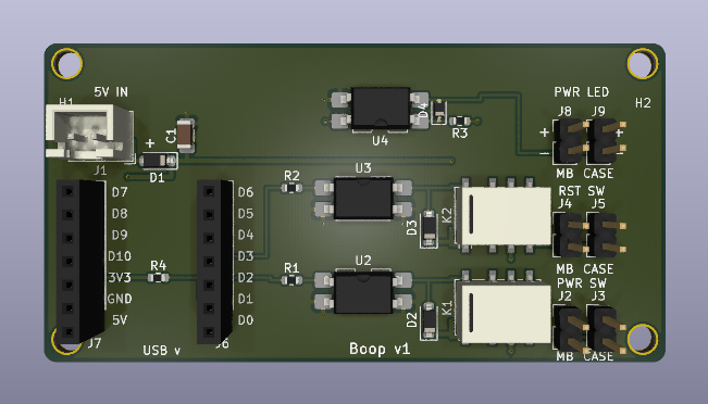
It carries a Seeed XIAO ESP32-C3 on sockets. Two relays sit in parallel with the front-panel power and reset buttons, so the real buttons keep working. A third input watches the power LED header so Home Assistant knows the state instead of guessing.
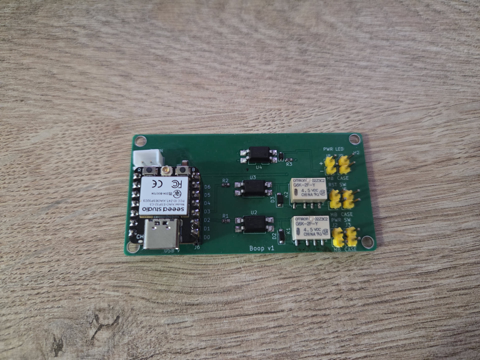
Status: designed and checked (ERC clean, DRC has no errors, JLCPCB's pre-flight passes). The first board has been built and soldered, and it works.
D2 (GPIO4) -> 150R -> opto -> relay K1 -> in parallel with the PWR button
D3 (GPIO5) -> 150R -> opto -> relay K2 -> in parallel with the RESET button
D1 (GPIO3) <- opto <- motherboard PWR LED header (low = PC is on)Heads up: for the PC to be startable from off, the motherboard USB 5 V has to stay alive in shutdown. Many boards turn it off unless you enable something like "USB standby power" or disable ErP in the BIOS. If yours cuts it, power the board from the USB-C instead.
All the 2-pin headers are 2.54 mm. The left column is always the motherboard side and the right column is always the case side, so it is the same on every pair.
| Ref | Label | Goes to |
|---|---|---|
| J1 | 5V IN | JST XH 2-pin, + and - are marked. Optional 5 V from the motherboard USB header (pin 1 VCC, pin 7 GND) |
| J2 | PWR SW / MB | motherboard power switch header |
| J3 | PWR SW / CASE | the case power button lead |
| J4 | RST SW / MB | motherboard reset header |
| J5 | RST SW / CASE | the case reset button lead |
| J8 | PWR LED / MB | motherboard power LED header, + marked |
| J9 | PWR LED / CASE | the case power LED lead, + marked |
| J6, J7 | XIAO | 1x7 female sockets, pin names are printed on the board |
The relay contacts are volt-free, so polarity on the button headers does not
matter. The LED pair does have a polarity, follow the +.
Four M3 holes in the corners for standoffs.
The full config is in boop-esphome.yaml. Pins are the XIAO
ESP32-C3 D-numbers: D1 = GPIO3, D2 = GPIO4, D3 = GPIO5.
It exposes three buttons to Home Assistant (power tap, power hold for force off, reset) and a "PC is on" sensor. The relays are internal and always start off, so a reboot can't hold a button down.
Create a secrets.yaml next to it with wifi_ssid, wifi_password,
boop_api_key (openssl rand -base64 32), boop_ota_password and
boop_ap_password, then flash the first time over USB:
esphome run boop-esphome.yamlIf the board isn't detected, hold BOOT, tap RESET, release BOOT. Unplug J1 (the motherboard 5 V) while flashing over USB-C. Later updates go over Wi-Fi.
Everything you need for JLCPCB is in fab/.
Copyright 2026 Dejan Noveski. Released under
CC BY-SA 4.0, the full text
is in LICENSE. In plain words: build it, sell it, change it, as long as you
credit me and share your changes under the same licence. That covers the
schematic, the board, the Gerbers, the script and the ESPHome example.
The exception is lib/, which holds trimmed copies of KiCad's stock libraries.
Those keep their own licence, see lib/NOTICE.md.
| Qty | Value | Footprint | References |
|---|---|---|---|
| 4 | MountingHole | MountingHole:MountingHole_3.2mm | H1, H2, H3, H4 |
| 2 | 150 | Resistor_SMD:R_0603_1608Metric | R1, R2 |
| 2 | 1N4148W | Diode_SMD:D_SOD-123 | D2, D3 |
| 2 | G6K-2F-Y-TR DC4.5 | Relay_SMD:Relay_DPDT_Omron_G6K-2F-Y | K1, K2 |
| 2 | LTV-817S-TA1-D | Package_DIP:SMDIP-4_W9.53mm | U2, U3 |
| 1 | 10k | Resistor_SMD:R_0603_1608Metric | R4 |
| 1 | 10uF 25V | Capacitor_SMD:C_1206_3216Metric | C1 |
| 1 | 1N4148WS | Diode_SMD:D_SOD-323 | D4 |
| 1 | 1N5819HW-7-F | Diode_SMD:D_SOD-123 | D1 |
| 1 | 470 | Resistor_SMD:R_0603_1608Metric | R3 |
| 1 | 5V_IN (+/-) | Connector_JST:JST_XH_B2B-XH-A_1x02_P2.50mm_Vertical | J1 |
| 1 | LTV-817S-TA1-C | Package_DIP:SMDIP-4_W9.53mm | U4 |
| 1 | PLED_FROM_MB | Connector_PinHeader_2.54mm:PinHeader_1x02_P2.54mm_Vertical | J8 |
| 1 | PLED_TO_CASE | Connector_PinHeader_2.54mm:PinHeader_1x02_P2.54mm_Vertical | J9 |
| 1 | PWR_FROM_CASE | Connector_PinHeader_2.54mm:PinHeader_1x02_P2.54mm_Vertical | J3 |
| 1 | PWR_TO_MB | Connector_PinHeader_2.54mm:PinHeader_1x02_P2.54mm_Vertical | J2 |
| 1 | RST_FROM_CASE | Connector_PinHeader_2.54mm:PinHeader_1x02_P2.54mm_Vertical | J5 |
| 1 | RST_TO_MB | Connector_PinHeader_2.54mm:PinHeader_1x02_P2.54mm_Vertical | J4 |
| 1 | XIAO_LEFT_D0-D6 | Connector_PinSocket_2.54mm:PinSocket_1x07_P2.54mm_Vertical | J6 |
| 1 | XIAO_RIGHT_5V-D7 | Connector_PinSocket_2.54mm:PinSocket_1x07_P2.54mm_Vertical | J7 |
It measures 74 × 38 mm and has 2 copper layers, 1.6 mm thick.
27 parts, built around the LTV-817S-TA1-D, LTV-817S-TA1-C, 1N4148W and 1N4148WS. The full list of its parts is on this page, with links to each part's symbol and footprint where PCBKit's library has them.
From the dekomote/boop repository on GitHub, at the commit this page was made from: the board is boop.kicad_pcb and its schematic boop.kicad_sch. PCBKit opens the board in the browser, with nothing to install.
Its repository publishes it under the CC-BY-SA-4.0 licence: you may reuse it on that licence's terms (keep the author's notice, and for a copyleft licence share your changes alike).

josearistidesbail/FE_UFPR_4_0
KiCad 10 project for the board that sits between a TI LAUNCHXL-F28379D (runs the FOC firmware) and an Infineon PrimeSTACK 6PS04512E43W39693 inverter driving an EMRAX 208 motor.

akladnig/CamperVan
- CamperVan Design and Arduino Circuit Design - Campervan Design Overview - Dashboard App - Electrical System - Sensors - Circuit Design - Battery and voltage monitoring - Voltage Divider Design - Low Pass Filter - TODO


WestianPKl/Logger_Dashboard
A full-stack IoT monitoring platform for collecting, visualizing, and managing environmental sensor data from distributed devices.

ssbingo/samba-solar-track
Samba Solar Track – Solarnachführung mit Sturmschutz: Handbuch, Platine und Gehäuse für den Nachbau (10,1-Zoll-Version)


WestianPKl/pcb-docs
A collection of custom PCB designs created in KiCAD, centered around the Raspberry Pi Pico (RP2040) platform. Each board is a standalone module that connects to the Main Board and extends its functionality via I2C, SPI…