
2 layers98 × 27 mm

 deiol/NES-PCB3
Clone of Nintendo NES power/reset switch PCB
NES SW-02 compat is an open-source printed circuit board by deiol, from the deiol/NES-PCB repository on GitHub, published under the GPL-3.0 licence. It is a 2-layer board of 65.5 × 28 mm with 5 parts on 5 nets, routed with 32 tracks and 0 vias.
It belongs with the retro computing and games boards of this library.


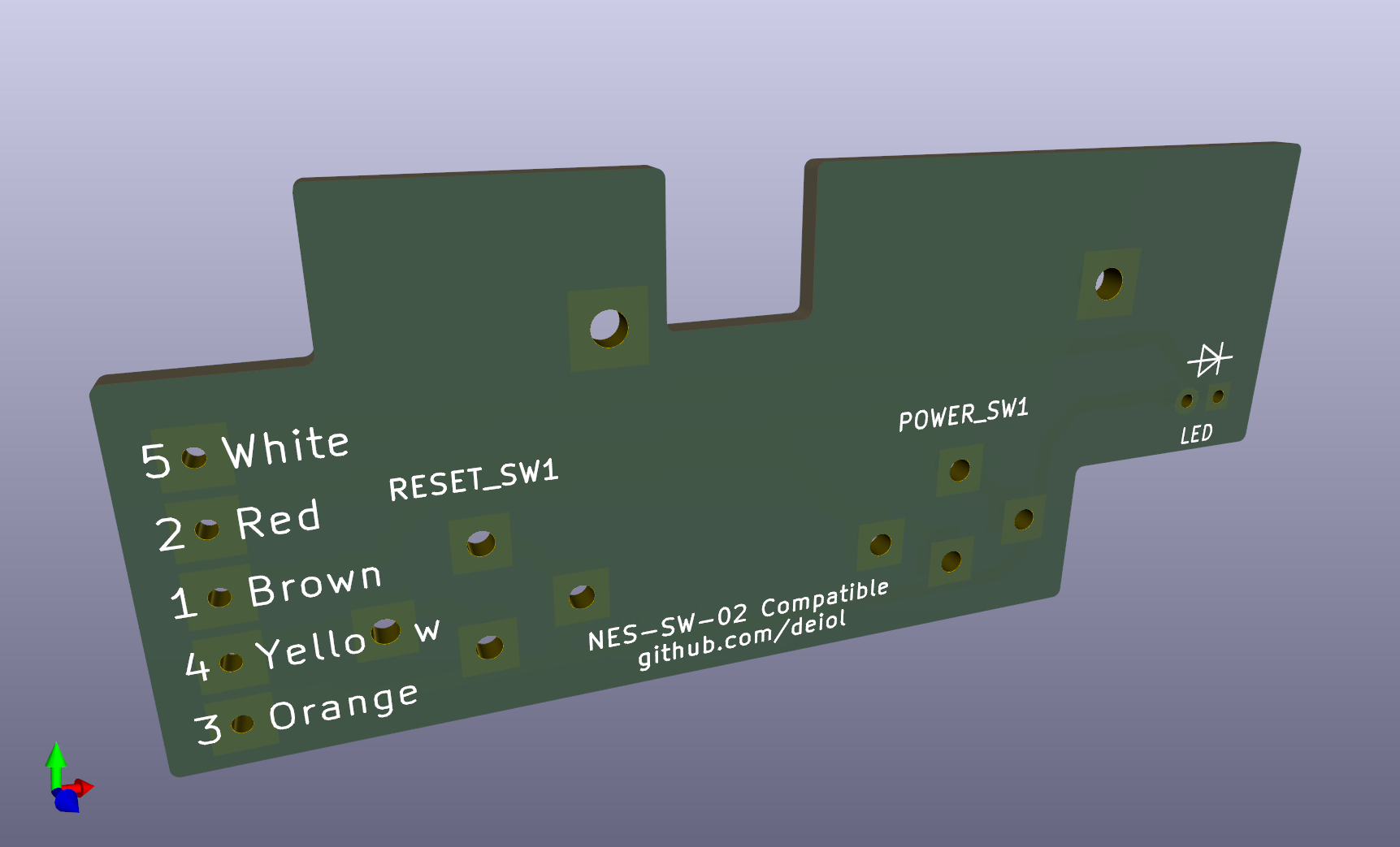
Based on a request and discussion in this r/NES thread, I created a drop-in replacement for the Power/Reset PCB from the front-loader Nintendo Entertainment System.
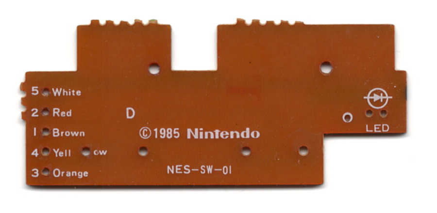
Taking a look at pictures online as well as NES consoles I had available, I realized there are at least two board revisions; NES-SW-01 and NES-SW-02 (if you've come across any other variants, please let me know).
NES-SW-01
NES-SW-02
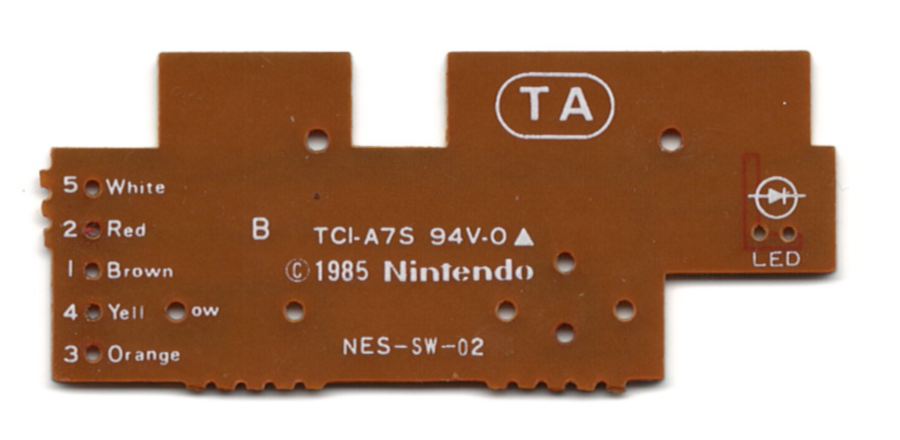
This design is based on the NES-SW-02 as it should be "backwards compatible" with the NES-SW-01.
Additionally, I used the same power switch footprint for the reset switch. This way you should be able to use either switch body type for the reset switch (although you'll want to use a momentary switch for reset, latching for power).
Board thickness is 1.6mm. Gerber and drill files are included in case they are helpful to anyone. They were created for production at JLCPCB following their gudiance on generating Gerber and Drill files in KiCAD 9. I only reference JLCPCB because I have used them in the past. You can of course have the board produced by a different manufacturer, some aspects of the board may need to be tweaked based on their requirements.
If you don't want to go through the trouble of getting boards manufactured, they are available for sale on Tindie or Ko-fi
I am not an electrical engineer, just a hobbyist. I couldn't find datasheets for any of the components, so the footprints were created from "scratch" using measurements taken with rulers and calipers. Similarly, the boards were measured with rulers and calipers and also compared against scans I took. Everything in this repo is offered as-is, use at your own risk.
2026-06-15 - I am currently working on another version of the board that will support aftermarket switches. I was hoping to be able to design a single board that would support both native and aftermarket switches. However, due to the way the native switches and board mount to the NES shell, this is not likely to be possible.
2026-05-07 - The board has been tested by multiple parties with no issues reported! Boards are available for sale on Tindie or Ko-fi.
2026-03-19 - Currently the board design is untested, I plan on ordering some prototypes and will update this repo after I see how they turn out. I will try to make any adjustments to the files as needed.
| Qty | Value | Footprint | References |
|---|---|---|---|
| 2 | SW_SPST | NES_Footprints:NES-SW-02 Switch | POWER_SW1, RESET_SW1 |
| 1 | Conn_01x05 | NES_Footprints:NES-SW-02 Connector | J1 |
| 1 | LED | LED_THT:LED_D5.0mm | LED |
The 4 most common of 5 parts.
It measures 65.5 × 28 mm and has 2 copper layers, 1.6 mm thick.
5 parts. The full list of its parts is on this page, with links to each part's symbol and footprint where PCBKit's library has them.
From the deiol/NES-PCB repository on GitHub, at the commit this page was made from: the board is NES-SW-02_compat.kicad_pcb and its schematic NES-SW-02_compat.kicad_sch. PCBKit opens the board in the browser, with nothing to install.
Its repository publishes it under the GPL-3.0 licence: you may reuse it on that licence's terms (keep the author's notice, and for a copyleft licence share your changes alike).

joypad-ai/joypad-os
Universal controller firmware for building adapters, dongles, and custom controllers.

OLIMEX/OLINUXINO
OLINUXINO is Open Source / Open Hardware, low cost from EUR 24 Linux Industrial grade Single Board Computer capable to operate -25+85C

jamro/tiny-engineer
A small desktop robot that brings an AI coding assistant to life, physically acting out when it reads files, thinks, writes code, and finishes work.

hackclub/OnBoard
💡 Join 1,000 teenagers and make your first PCB with a $100 grant!


Luos-io/luos_engine
Open-source and real-time orchestrator for cyber-physical-systems, to easily design, test and deploy embedded applications and digital twins.