Skip to the content
2 layers225 × 35.6 mmLemmingometre, the printed circuit board in 3D

Lemmingometre

DCC-Lab/Lemming1

LEM: Lemming Enumeration Module

Size
225 × 35.6 mm
Copper layers
2
Thickness
1.6 mm
Parts
5
Nets
36
Pads
45
Tracks, vias
41, 0
Routed
Yes
KiCad
KiCad 7 (file 20221018)
Created
7 Jul 2023
Updated
12 Feb 2026

Overview

Lemmingometre is an open-source printed circuit board by DCC-Lab, from the DCC-Lab/Lemming repository on GitHub. It is a 2-layer board of 225 × 35.6 mm with 5 parts on 36 nets, routed with 41 tracks and 0 vias.

Its parts include 3 connectors and 1 IC.

README

README.md

LEM: Lemming Enumeration Module

Authors: Authors: Gabriel Bergeron*, Mireille Quémener*, Thomas Shooner, Christopher Mathault, Nathan Bérubé, Daniel Côté, Dominique Fauteux, Pierre Legagneux

Context

This project focuses on the development of a monitoring device for small mammals, specifically targeting the lemming. The device is designed for deployment in extreme environments, such as the Arctic.

How it works

The LEM functions as a passive event logger using an infrared sensor to detect the passage of small mammals, who emmit IR radiation.

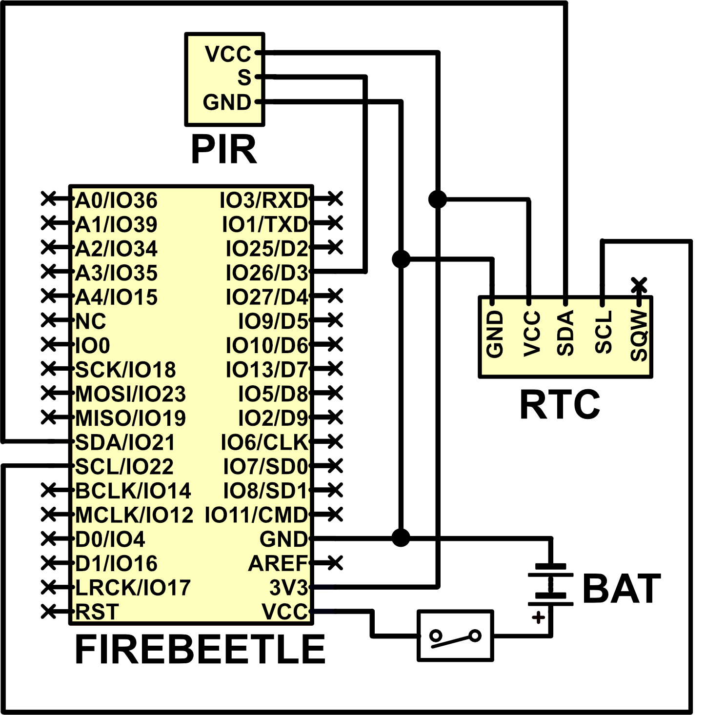
  • Detection Trigger: The device uses a Passive Infrared (PIR) sensor (AM312) positioned at the intersection of the tunnel and the electronics enclosure. When a small mammal enters the tube, its body heat creates a thermal contrast that triggers the sensor.
  • Wake-on-Interrupt: To minimize battery consumption, the microcontroller remains in a "deep sleep" state. The PIR sensor is the only component that actively wakes the FireBeetle ESP32 by sending a high signal to a specific I/O pin when motion is detected.
  • Data Logging: Once awakened, the system immediately pulls a precise date and time from the Real-Time Clock (RTC). This information is saved as a single timestamp entry in the onboard SPIFFS (Serial Peripheral Interface Flash File System) memory. The RTC ensures long-term accurate time keeping even in cold weather.
  • No Species Identification: It is important to note that the sensor is species-blind; it records the presence of an animal based on heat and motion but cannot distinguish between different small mammals, such as brown lemmings, collared lemmings, or shrews.

Mechanical Assembly

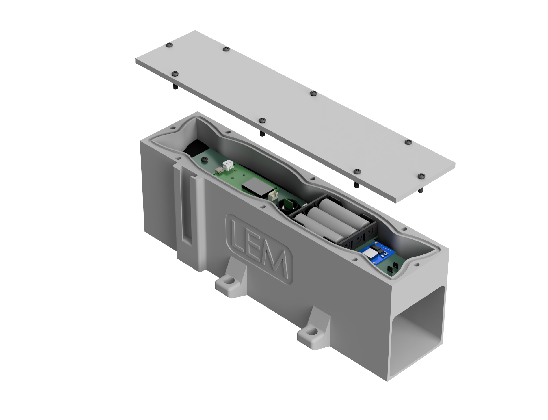
The LEM device is designed as single-unit instrument to withstand extreme Arctic conditions, including flooding, permafrost, and sub-zero temperatures.

  • Main body: of a $2.5 \times 2.5$ inch rectangular tunnel integrated with a top-mounted electronics enclosure. The unit is manufactured via thermoplastic molding using black MD-70 polyurethane elastomer, chosen for its durability and resistance to UV degradation and extreme temperatures.
  • Waterproofing: The electronics lid is secured with screws and sealed against a rubber gasket. The PIR sensor and the power switch are further sealed into the chassis using epoxy resin to prevent water infiltration.
  • Deployment: The device is placed directly on the ground and secured along small mammal paths using metal pegs. Its tunnel dimensions are specifically designed to be compatible with existing live-traps to ensure consistent animal usage probabilities.

Electronic System

The LEM circuit is optimized for ultra-low power consumption, enabling autonomous operation in remote environments for over a year on standard AA alkaline batteries.

  • Microcontroller: we selected the DFRobot FireBeetle ESP32-E for its deep-sleep capabilities and 1mW standby power draw (for the circuit in this project).
  • Sensing: Uses an AM312 Passive Infrared (PIR) sensor. When motion is detected in the tunnel, the PIR signal wakes the microcontroller to log the event.
  • Data Logging: Each detection is recorded as a time-stamped entry in the FireBeetle’s onboard SPIFFS memory.
  • Timekeeping: Includes an Adafruit PCF8523 Real-Time Clock (RTC) module powered by a dedicated lithium coin cell to maintain accurate time across deep-sleep cycles and cold-induced power fluctuations.
  • Power Supply: Operates on three AA alkaline batteries (4.5V total). Field tests show the system can maintain sufficient voltage for over 390 days of operation at average temperatures of -9°C.
  • Interface: Features a waterproof external rocker switch (ZF Electronics KRE2ANA1BBD) for field activation/deactivation. Data is retrieved via a standard USB connection to the FireBeetle.
  • Custom PCB: a custom PCB was designed for the spectific needs of this project.

What you will find in this repository

Important: The LEM device deployed at Bylot Island represents Version 3. For the record, two previous prototypes were designed and tested before converging on this final iteration.

Codes

All Arduino-based source code required for field deployment is located in Code/v3/SPIFFS_PCF8523. If you are using the DS1307 RTC module instead of the PCF8523, use the version found in Code/v3/SPIFFS_DS1307.

The workflow is divided into three distinct phases to match the deployment cycle:

  • Initialization (init_lem_v3_pcf8523): This code is uploaded to the FireBeetle before field deployment to reinitialize the system and wipe all existing data from the SPIFFS memory. This should be run prior to every new deployment.
  • Deployment (main_lem_v3_pcf8523): Once initialized, upload this code to place the device into "deployment mode". When the rocker switch is toggled on, the device creates a "startFile" with a timestamp to mark the beginning of the session and begins logging lemming activity. Every power cycle (off/on) generates a new timestamped "startFile".
  • Data Retrieval (read_lem_v3_pcf8523): After retrieving the device from the field and powering it down, upload this code to output the stored SPIFFS data to the serial terminal.

Data Downloader Utility: After uploading the retrieval code, you can use our standalone desktop utility (available for Windows 64-bit) to download data directly to your computer. This utility includes a simple UI to select the FireBeetle's COM port and your destination folder. You can find this program under the Releases section.

CAD files

The CAD folder contains STEP files of the full LEM assembly. Native project files (Fusion360 or SolidWorks) are available upon request.

PCB files

Gerber files for the PCB are located in PCB/LEM_v3/gerberFiles.

Parts

5
QtyValueFootprintReferences
1LOGOCustom components:LEMG***
1PIR1Connector_PinHeader_2.54mm:PinHeader_1x03_P2.54mm_VerticalJ3
1PIR2Connector_PinHeader_2.54mm:PinHeader_1x03_P2.54mm_VerticalJ2
1PIR3Connector_PinHeader_2.54mm:PinHeader_1x03_P2.54mm_VerticalJ1
1~Custom components:FirebeetleU1

More from DCC-Lab/Lemming

2
  • 2 layers30.6 × 77.6 mmLemmingometre, the printed circuit board in 3D

    Lemmingometre

    DCC-Lab/Lemming

    LEM: Lemming Enumeration Module

    16 parts1
  • 2 layers30.6 × 77.6 mmLemmingometre JST, the printed circuit board in 3D

    Lemmingometre JST

    DCC-Lab/Lemming

    LEM: Lemming Enumeration Module

    16 parts1

Similar boards

  • 2 layers98 × 27 mmXy limit, the printed circuit board in 3D

    Xy limit

    opulo-inc/lumenpnp

    The LumenPnP is an open source pick and place machine.

    5 parts3.7k
  • 2 layers21 × 33 mm24g2usb pico2w, the printed circuit board in 3D

    24g2usb pico2w

    joypad-ai/joypad-os

    Universal controller firmware for building adapters, dongles, and custom controllers.

    5 parts1.7kApache-2.0
  • 2 layers53.2 × 59.6 mmA10 OLinuXino Lime Rev B SHIELD TEMPLATE, the printed circuit board in 3D

    A10 OLinuXino Lime Rev B SHIELD TEMPLATE

    OLIMEX/OLINUXINO

    OLINUXINO is Open Source / Open Hardware, low cost from EUR 24 Linux Industrial grade Single Board Computer capable to operate -25+85C

    5 parts1.5k
  • 2 layers30 × 11 mmMain control board servo tester, the printed circuit board in 3D

    Main control board servo tester

    jamro/tiny-engineer

    A small desktop robot that brings an AI coding assistant to life, physically acting out when it reads files, thinks, writes code, and finishes work.

    5 parts1.1k
  • 2 layers78.8 × 35.3 mmKiCadTest, the printed circuit board in 3D

    KiCadTest

    hackclub/OnBoard

    💡 Join 1,000 teenagers and make your first PCB with a $100 grant!

    5 parts915
  • 2 layers50 × 23 mmMiniCircuits LTCC, the printed circuit board in 3D

    MiniCircuits LTCC

    VanceVagell/kv4p-ht

    Open source handheld ham radio project KV4P-HT

    5 parts828GPL-3.0
  • 2 layers20.3 × 15.2 mmL0 light sensor, the printed circuit board in 3D

    L0 light sensor

    Luos-io/luos_engine

    Open-source and real-time orchestrator for cyber-physical-systems, to easily design, test and deploy embedded applications and digital twins.

    5 parts546MIT

Questions

How big is the Lemmingometre PCB?

It measures 225 × 35.6 mm and has 2 copper layers, 1.6 mm thick.

What parts does the Lemmingometre use?

5 parts. The full list of its parts is on this page, with links to each part's symbol and footprint where PCBKit's library has them.

Where can I download the Lemmingometre KiCad files?

From the DCC-Lab/Lemming repository on GitHub, at the commit this page was made from: the board is Circuit/v2/PCB_firebeetle/Lemmingometre/Lemmingometre.kicad_pcb and its schematic Circuit/v1/PCB/Lemmingometre.kicad_sch. PCBKit opens the board in the browser, with nothing to install.

Can I use the Lemmingometre design in my own project?

Its repository states no licence, so its author keeps all rights: ask DCC-Lab before reusing the design.