4 layers241.8 × 174.8 mm
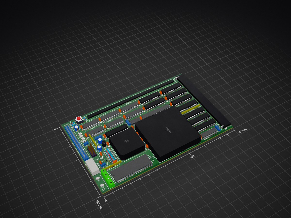
 danwerner21/SBC80386EX1
ECB 80386EX sbc
SBC-386EX-2 is an open-source printed circuit board by danwerner21, from the danwerner21/SBC80386EX repository on GitHub. It is a 4-layer board of 160 × 100 mm with 96 parts on 215 nets, routed with 4,776 tracks and 99 vias.
It is built around the 74LS240DC, 74LS245SC and 74LS241P-E, with the 74F257APC, 74HCT14D and 74LS74PC among its other parts. Its parts include 39 capacitors, 24 ICs, 9 connectors, 8 resistors and 8 diodes. It belongs with the computers and single-board computers boards and the FPGA and CPLD boards of this library.


A single board computer built around the Intel 80386EX, an embedded 386 with most of a PC's support chips on the die. It plugs into a RetroBrew ECB backplane or runs on its own, and with the BIOS in this repository it boots MS-DOS 6.22 and COHERENT 4.2, Mark Williams Company's UNIX-like operating system.
The board was designed by John Coffman for RetroBrew Computers. Its project page, with the boards, the history and the community around it, is the SBC-386EX wiki page. This repository holds the board's design files, its BIOS, and the software that runs on it.
Version 2.0, from John Coffman's guide to the schematic
(Hardware/SBC386ex2-schematic-guide.pdf):
| CPU | Intel 80386EX, up to 33 MHz (a 66 MHz double-frequency oscillator for the fastest parts); on the board, or on an adapter board, the two footprints overlaid |
| FPU | 80387SX socket, run at the CPU's clock |
| Memory | one 72-pin SIMM, 4 to 64 MB, FPM or EDO, through a DRAM controller in two GAL16V8s; provision for a 32 KB static RAM |
| ROM | 64 KB EPROM, or 128, 256 or 512 KB flash, chosen by jumper |
| Serial | the 386EX's SIO0 at 3F8h, RS-232 on a 9-pin connector, from a 1.8432 MHz clock |
| Disk | an IDE connector laid out for a CompactFlash adapter, 8-bit programmed I/O |
| Clock | DS1302 real-time clock with battery-backed NVRAM |
| SD card | a microSD socket on the 386EX's synchronous serial unit (described on the schematic as "entirely experimental"; it works: see below) |
| Bus | 96-pin ECB connector, for RetroBrew cards: the Disk I/O V3 floppy controller, the VGA3 video and PS/2 keyboard board, and others |
| Front panel | four LEDs on port 1, a run/halt LED, reset |
The KiCad project, the schematic and board PDFs, a bill of materials and
the PLD equations are in Hardware/.
SBC386/bios is the board's ROM BIOS: John Coffman's,
from 2018, which brought the board up and laid the foundations, taken by
Dan Werner in 2026 to the point where it boots DOS. It gives the board a
PC-compatible BIOS interface on hardware that is not a PC:
Notes for using it are in SBC386/bios/0README.TXT.
Two worth knowing first: three Ctrl-^ in a row on the serial console
restart the board (it has no Ctrl-Alt-Del), and HIMEM.SYS needs
/MACHINE:PS2, since there is no 8042 for it to drive A20 through.
How the BIOS went from never having run INT 13h to a DOS prompt, and why
things are as they are, is told in 0BRINGUP.md; what is
left is 0TODO.md.
The build runs on Linux. It needs:
| GNU make | |
| NASM | 2.08 is the version used; 2.09 is reported to have problems |
| Open Watcom C 1.9 | its tools on the PATH, and WATCOM set to where it is installed |
| gcc | for the build's helper programs |
The helper programs (exe2rom, hex2bin, bin2hex, copt) are
in SBC386/tools, with their sources. Build them if the ones there do
not run on your system:
cd SBC386/tools
make
The ROM:
cd SBC386/bios
make
This builds rom064.hex, the 64 KB image for an EPROM, and
rom128.hex, rom256.hex and rom512.hex, the same BIOS placed at
the top of a 128, 256 or 512 KB flash part. They are Intel HEX, for
any device programmer. make MONITOR=0 leaves the debug monitor out,
which frees about 25 KB of the 64 KB.
Program the part that matches the ROM jumper, fit it, and connect a terminal to the serial port at 9600 baud, 8 data bits, no parity. POST runs there; press a key during it for SETUP.
SBC386/sdcard has a DOS driver for the on-board
microSD socket, and the program it was brought up with:
SD.SYS: DEVICE=SD.SYS in CONFIG.SYS gives the card's first
FAT12 or FAT16 partition a drive letter (DOS 4 or later)SDTEST.COM: the bring-up program, which tests the socket a step
at a time, from the pins to timed reads and a write test on a sector
outside the partitionBoth build with make in that directory (GNU make and NASM). How the
socket was made to work, given a serial unit that only moves 16-bit
words and a clock line that floats between transfers, is set down in the
comments of sdtest.asm.
Coherent/ is a port of COHERENT 4.2 to the board. It
comes up multi-user, with a login on the serial port and another on the
VGA3 screen and keyboard when one is fitted. Its drivers cover the
board's IDE port and CompactFlash, the ECB floppy controller (read,
write and format), the VGA3 console, and the microSD socket, so files
move to and from DOS on SD cards and diskettes.
It is installed on the board from five diskettes, the original 4.2.10
kit with a boot diskette and a supplement made for the board. The
diskette images, the installation directions and everything about
building it are in Coherent/README.md.
| Path | |
|---|---|
Hardware/ | the board: KiCad project, schematic and PCB PDFs, the schematic guide, bill of materials, PLD equations |
SBC386/bios/ | the BIOS |
SBC386/tools/ | the BIOS build's helper programs and their sources |
SBC386/sdcard/ | SD.SYS and SDTEST.COM, for the microSD socket under DOS |
SBC386/ATBIOS/ | an IBM AT BIOS listing, the reference for what DOS expects |
Coherent/ | the COHERENT port: install diskettes, kernel source and changes, tools |
TestROMS/, EX2-11/, 386v2/ | John Coffman's test ROMs, early BIOS work and PLD files from the board's bring-up in 2018 |
0BRINGUP.md, 0TODO.md | the BIOS bring-up record, and what is left |
The BIOS is free software under the GNU General Public License, version
3 or later: see SBC386/bios/COPYING. COHERENT's
own licence, and that of the work on it here, are described in
Coherent/README.md.
| Qty | Value | Footprint | References |
|---|---|---|---|
| 28 | C | Capacitors_ThroughHole:C_Disc_D5.0mm_W2.5mm_P5.00mm | C10, C11, C12, C13, C14, C15, C16, C17, C18, C19, C20, C21, C22, C23, C24, C25 +12 |
| 5 | 10uF | Capacitors_ThroughHole:CP_Radial_D5.0mm_P2.00mm | C43, C44, C45, C46, C47 |
| 4 | LED | LEDs:LED_D3.0mm | D3, D4, D5, D6 |
| 3 | 74ALS244 | dip_sockets:DIP-20__300 | U11, U12, U13 |
| 3 | 74F257 | dip_sockets:DIP-16__300 | U19, U20, U21 |
| 3 | Conn_01x03 | pin_array:PIN_ARRAY_3X1 | J1, J3, J4 |
| 3 | GAL16V8 | dip_sockets:DIP-20__300 | U18, U22, U23 |
| 2 | 10K | discret:r_pack9 | RR1, RR2 |
| 2 | 22uF | Capacitors_ThroughHole:CP_Radial_D8.0mm_P2.50mm | C1, C2 |
| 2 | 2700 | discret:R3 | R5, R6 |
| 2 | 4700 | discret:R3 | R7, R8 |
| 1 | 0.1 | Capacitors_ThroughHole:C_Disc_D5.0mm_W2.5mm_P5.00mm | C42 |
| 1 | 10 | discret:R3 | R2 |
| 1 | 10K | 01N8VEM:r_pack4 | RR5 |
| 1 | 10k | discret:R3 | R3 |
| 1 | 10uf | Capacitors_ThroughHole:CP_Radial_D5.0mm_P2.00mm | C3 |
| 1 | 1N4148 | discret:D3 | D7 |
| 1 | 270 | discret:R3 | R4 |
| 1 | 29F040 | dip_sockets:DIP-32__600 | U6 |
| 1 | 4.7uF | Capacitors_ThroughHole:CP_Radial_D5.0mm_P2.00mm | C41 |
| 1 | 470 | 01N8VEM:r_pack4 | RR3 |
| 1 | 68 | discret:R3 | R1 |
| 1 | 74HCT14 | dip_sockets:DIP-14__300 | U9 |
| 1 | 74LS240 | dip_sockets:DIP-20__300 | U14 |
| 1 | 74LS241 | dip_sockets:DIP-20__300 | U3 |
| 1 | 74LS245 | dip_sockets:DIP-20__300 | U10 |
| 1 | 74LS74 | dip_sockets:DIP-14__300 | U15 |
| 1 | C96ABC | 01N8VEM:C96ABCM-RA | ECB1 |
| 1 | CLK-1.8432 | dip_sockets:DIP-14__300 | U17 |
| 1 | CONN_2 | pin_array:PIN_ARRAY_2X1 | P4 |
| 1 | CPU-66mhz | dip_sockets:DIP-14__300 | U16 |
| 1 | CRYSTAL | Kicad:Tuning_Fork_Header_Straight_1x02_Pitch1.00mm | X1 |
| 1 | Conn_01x02 | pin_array:PIN_ARRAY_2X1 | J5 |
| 1 | Conn_01x04 | 01N8VEM:PCpower4 | P1 |
| 1 | Conn_02x05_Odd_Even | 01N8VEM:SHROUDED_5x2 | J2 |
| 1 | Conn_02x20_Odd_Even | Kicad:SHROUDED_20X2 | P3 |
| 1 | DIODE | discret:D3 | D2 |
| 1 | DS1302 | dip_sockets:DIP-8__300 | U8 |
| 1 | I386EX_PQFP | Kicad:PQFP-132_i386_JRC | U101 |
| 1 | I386EX_passive | Kicad:i386EX-132-adapter | U1 |
| 1 | LP2950-3.3_TO92 | TO_SOT_Packages_THT:TO-92_Inline_Narrow_Oval | U5 |
| 1 | MAX233 | dip_sockets:DIP-20__300 | U7 |
| 1 | MT16D832 | 01N8VEM:DRAM-72-2021 | SIM1 |
| 1 | R/G LED | LEDs:LED_D3.0mm | D1 |
| 1 | SD LED | LEDs:LED_D3.0mm | D8 |
| 1 | SRAM-32K | dip_sockets:DIP-28__300 | U4 |
| 1 | SUPER | 01N8VEM:SuperCap5 | C4 |
| 1 | SW_PUSH | discret:SW_PUSH_SMALL | SW1 |
| 1 | i387SX | Kicad:80188 | U2 |
| 1 | microSD-01 | Kicad:microSD-Molex-47309 | P2 |


raymondh2/CompaqPortableIII
Current PCB Memory Expansion board layout is untested. The backplane for the expansion cards is tested and working.


NeilsVintageComputers/1981_Aamber-Pegasus-2023-Revival
My first computer, this is a replica I produced from the original schematics using original old components.

lynchaj/rhyophyre
Single Board Computer featuring Zilog Z180 processor and NEC µPD7220 Graphics Display Controller


It measures 160 × 100 mm and has 4 copper layers, 1.6 mm thick.
96 parts, built around the 74LS240DC, 74LS245SC, 74LS241P-E and 74F257APC. The full list of its parts is on this page, with links to each part's symbol and footprint where PCBKit's library has them.
From the danwerner21/SBC80386EX repository on GitHub, at the commit this page was made from: the board is Hardware/SBC-386EX-2.0-kicad/SBC-386EX-2.kicad_pcb. PCBKit opens the board in the browser, with nothing to install.
Its repository states no licence, so its author keeps all rights: ask danwerner21 before reusing the design.