2 layers118.7 × 168.3 mm
 danielpchamoun/DMClock
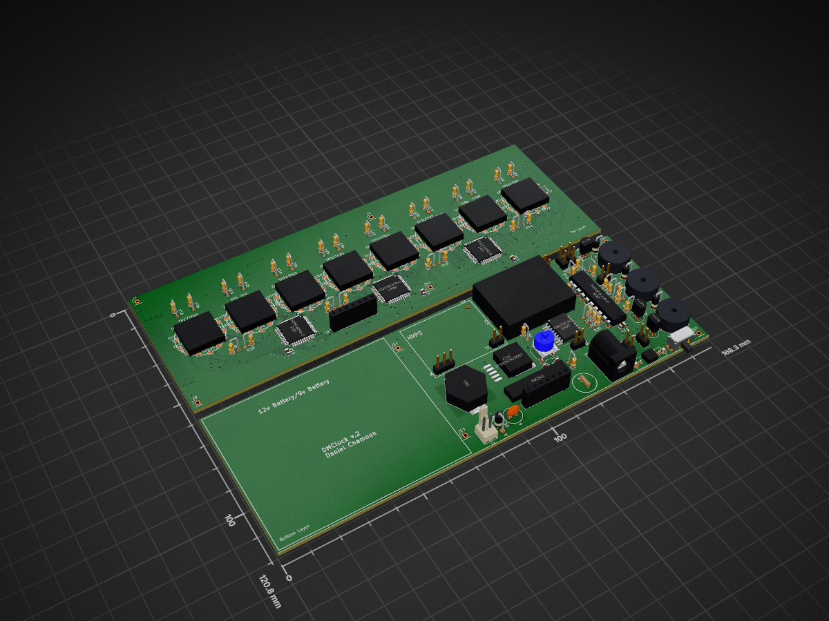
DMClock is an open-source printed circuit board by danielpchamoun, from the danielpchamoun/DMClock repository on GitHub. It is a 2-layer board of 168.3 × 120.8 mm with 204 parts on 171 nets, routed with 1,469 tracks and 227 vias.
It is built around the HV5622PG-G, DS3231SN#T&R and 2SC1815, with the CPT-1255C-090 among its other parts. Its parts include 39 resistors, 14 connectors, 9 capacitors, 9 switches and 6 ICs. It belongs with the PIC boards of this library.


| Qty | Value | Footprint | References |
|---|---|---|---|
| 104 | TestPoint | TestPoint:TestPoint_Pad_D1.5mm | TP1, TP10, TP11, TP12, TP13, TP14, TP15, TP16, TP17, TP18, TP19, TP100, TP101, TP102, TP103, TP104 +88 |
| 24 | R | Resistor_THT:R_Axial_DIN0204_L3.6mm_D1.6mm_P2.54mm_Vertical | R10, R11, R12, R13, R14, R15, R16, R17, R18, R19, R20, R21, R22, R23, R24, R25 +8 |
| 11 | 4.7K | Resistor_THT:R_Axial_DIN0204_L3.6mm_D1.6mm_P2.54mm_Vertical | R1, R2, R3, R5, R6, R36, R37, R39, R40, R41, R42 |
| 8 | Conn_01x01 | Connector_PinHeader_2.54mm:PinHeader_1x01_P2.54mm_Vertical | J7, J8, J9, J10, J11, J12, J13, J14 |
| 8 | IN-14 | nixies-us:nixies-us-IN-14 | NA1, NB1, NC1, ND1, NE1, NF1, NG1, NH1 |
| 7 | SW_Push | Connector_PinHeader_2.54mm:PinHeader_1x02_P2.54mm_Vertical | SW1, SW4, SW5, SW6, SW7, SW8, SW9 |
| 6 | 0.1uF | Capacitor_SMD:C_0805_2012Metric | C1, C10, C11, C12, C13, C14 |
| 4 | D | Diode_THT:D_A-405_P2.54mm_Vertical_AnodeUp | D1, D2, D3, D4 |
| 3 | 180 | Resistor_THT:R_Axial_DIN0204_L3.6mm_D1.6mm_P2.54mm_Vertical | R34, R35, R38 |
| 3 | 2SC1815 | Package_TO_SOT_THT:TO-92_Inline | Q1, Q2, Q3 |
| 3 | CPT-1255C-090 | Footprints:CUI_CPT-1255C-090 | LS1, LS2, LS3 |
| 3 | HV5622PG-G | Footprints:QFP44_10x10MC_MCH | U3, U4, U5 |
| 2 | Conn_01x07_Pin | Connector_PinSocket_2.54mm:PinSocket_1x07_P2.54mm_Vertical | J5, J6 |
| 1 | (12v LiPo battery) | Connector_Molex:Molex_KK-254_AE-6410-02A_1x02_P2.54mm_Vertical | J2 |
| 1 | 100uF | Footprints:CAPPRD350W60D825H1300 | C3 |
| 1 | 103 | Footprints:BAT_103 | BT1 |
| 1 | 1K | Resistor_THT:R_Axial_DIN0204_L3.6mm_D1.6mm_P2.54mm_Vertical | R4 |
| 1 | 1N5822 | Footprints:DIOAD2120W130L950D530P | D5 |
| 1 | 220uF | Footprints:WCAP-ATG8_6.3X11_DXL_ | C2 |
| 1 | 33uH | Footprints:DO5040H333MLD | L1 |
| 1 | 50k_Potentiometer | Footprints:TRIM_3306F-1-503 | RV1 |
| 1 | 5nF | Capacitor_SMD:C_0805_2012Metric | C4 |
| 1 | Barrel_Jack_Switch | Connector_BarrelJack:BarrelJack_Horizontal | J1 |
| 1 | Conn_01x02 | Connector_PinHeader_2.54mm:PinHeader_1x02_P2.54mm_Vertical | J3 |
| 1 | Conn_01x03 | Connector_PinHeader_2.54mm:PinHeader_1x03_P2.54mm_Vertical | J4 |
| 1 | DS3231SN_ | Footprints:SOIC127P1032X265-16N | U2 |
| 1 | LM2596DSADJG | Footprints:NCP5663DSADJR4G | U7 |
| 1 | MountingHole | MountingHole:MountingHole_2.2mm_M2 | Z9 |
| 1 | PIC16F18346-P | Package_DIP:DIP-20_W7.62mm | U1 |
| 1 | SW_SP3T (mode select) | Footprints:OS102011MS8QP1 | SW3 |
| 1 | SW_SPDT | Button_Switch_THT:SW_CuK_OS102011MA1QN1_SPDT_Angled | SW2 |
It measures 168.3 × 120.8 mm and has 2 copper layers, 1.6 mm thick.
204 parts, built around the HV5622PG-G, DS3231SN#T&R, 2SC1815 and CPT-1255C-090. The full list of its parts is on this page, with links to each part's symbol and footprint where PCBKit's library has them.
From the danielpchamoun/DMClock repository on GitHub, at the commit this page was made from: the board is DMClock/DMClock.kicad_pcb and its schematic DMClock/DMClock.kicad_sch. PCBKit opens the board in the browser, with nothing to install.
Its repository states no licence, so its author keeps all rights: ask danielpchamoun before reusing the design.


danpham/nixie_clock
ESP32-C3 Nixie clock using IN14/IN3 tubes and HV5622 driver.


waicool20/Divergence-Meter-Project-v2
This is the second iteration of the Divergence Meter Project and another personal learning project, this time learning how to integrate Li-Ion batteries into a project, new electrical converter topologies, Rust…


kuvychko/universal-nixie-display
Six IN-14 Nixie tubes, an A101 dekatron and an ESP32 touchscreen in one desktop display: a clock, timer and toy, and a numeric display for a computer over USB.

sportiduino/sportiduino
Electronic timing system for orienteering and similar outdoor sports events on Arduino