2 layers56 × 65 mm
SeaTalk1
dotnet/iot
This repo includes .NET Core implementations for various IoT boards, chips, displays and PCBs.
24 parts2.4kMIT

 DanielJaehaLee/Kiyburd
Spilt 40% ortholinear diode-less mechanical keyboard
Kiyburd is an open-source printed circuit board by DanielJaehaLee, from the DanielJaehaLee/Kiyburd repository on GitHub. It is a 2-layer board of 146 × 78 mm with 24 parts on 40 nets, routed with 290 tracks and 12 vias.
Its parts include 22 switches and 2 ICs. It belongs with the keyboards and input boards and the RP2040 boards of this library.
Split 40% ortholinear diode-less mechanical keyboard
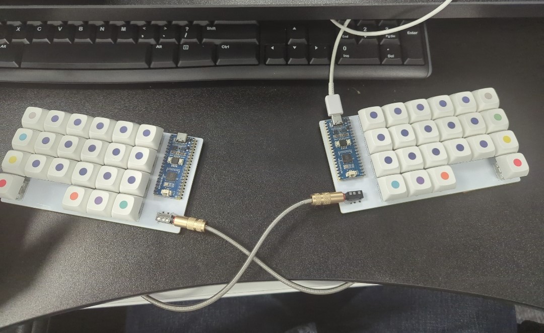
Kiyburd is a split keyboard built around a 44-key ortholinear grid, direct-pin wiring (no diode matrix), and a pair of Raspberry Pi Picos talking over TRRS. The goal is a compact, stabilizer-free board that is easier to wire and firmware-tune than a conventional matrix keyboard, without giving up QMK features.
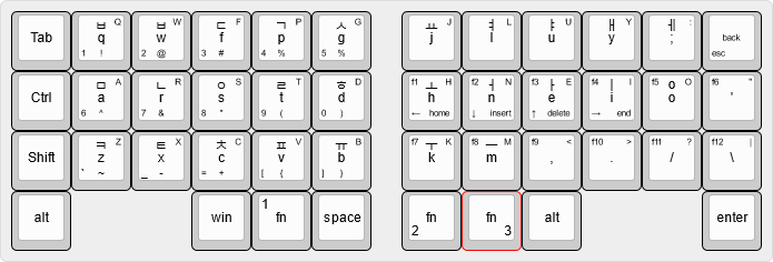
| Form factor | Split 40% · 22 keys per half · 44 keys total |
| Grid | Ortholinear 1u keys · no stabilized keys |
| Scanning | Direct GPIO (diode-less / matrix-less) |
| MCU | Raspberry Pi Pico (RP2040) × 2 |
| Inter-half link | TRRS (PJ-320A) · full-duplex USART |
| Firmware | QMK |
| PCB | Reversible |
| Status | PCB designed and ordered · QMK port working · case and Vial still open |
Most 40% boards still carry a row/column matrix, diodes, and at least a few 2u keys that need stabilizers. Kiyburd drops those on purpose:
The default firmware keymap is QWERTY with three extra layers (function keys, numbers/arrows, symbols/nav). The files under keyboard layout/ also document an experimental layered map with Hangul legends.
Kiyburd/
├── Firmware/                 QMK keyboard definition
│   ├── config.h              RP2040 bootloader + USART pins
│   ├── info.json             Matrix pins, USB IDs, layout geometry
│   ├── kiyburd.h             LAYOUT() macro
│   ├── rules.mk              RP2040 + split keyboard
│   └── keymaps/default/      QWERTY + Lower / Raise / Raise2
├── PCB/Kiyburd/              KiCad 7/8 project
│   ├── Kiyburd.kicad_sch
│   ├── Kiyburd.kicad_pcb
│   └── production/           BOM, CPL, Gerbers (Kiyburd.zip)
└── keyboard layout/ Keyboard Layout Editor JSON / SVG / PNG| Qty | Part | Notes |
|---|---|---|
| 1 | Raspberry Pi Pico (RP2040) | Socket or solder; USB-C or Micro-USB depending on Pico revision |
| 1 | PJ-320A TRRS jack | Inter-half serial + GND |
| 22 | Cherry MX compatible switches | 5-pin preferred; footprint is SW_Cherry_MX_1.00u_PCB_reversible |
| 22 | 1u keycaps | No 2u / no stabs |
| 1 | TRRS cable | Tip-ring-ring-sleeve; not a TRS headphone cable |
Build two halves. The PCB is reversible: the Pico and TRRS footprints are placed so the same board works as left or right.
Each switch is wired to one GPIO. Left and right halves mirror each other.
Left half
| Row | Col 0 | Col 1 | Col 2 | Col 3 | Col 4 | Col 5 |
|---|---|---|---|---|---|---|
| 0 | GP7 | GP6 | GP5 | GP4 | GP3 | GP2 |
| 1 | GP13 | GP12 | GP11 | GP10 | GP9 | GP8 |
| 2 | GP22 | GP26 | GP27 | GP28 | GP15 | GP14 |
| 3 | GP18 | — | — | GP19 | GP20 | GP21 |
Right half
| Row | Col 0 | Col 1 | Col 2 | Col 3 | Col 4 | Col 5 |
|---|---|---|---|---|---|---|
| 0 | GP2 | GP3 | GP4 | GP5 | GP6 | GP7 |
| 1 | GP8 | GP9 | GP10 | GP11 | GP12 | GP13 |
| 2 | GP14 | GP15 | GP28 | GP27 | GP26 | GP22 |
| 3 | GP21 | GP20 | GP19 | — | — | GP18 |
Split serial is full-duplex USART on the Pico's vendor serial driver:
| Signal | Pin |
|---|---|
| TX | GP1 |
| RX | GP0 |
Handedness defaults to left-as-master. Uncomment #define MASTER_RIGHT in Firmware/config.h if the right half should own USB.
Gerbers and assembly files live in PCB/Kiyburd/production/:
Kiyburd.zip — Gerber/drill packagebom.csv — bill of materialspositions.csv — pick-and-placedesignators.csv / netlist.ipcOpen PCB/Kiyburd/Kiyburd.kicad_pro in KiCad to edit the board before re-exporting.
Firmware is a QMK keyboard named kiyburd. It targets the RP2040 bootloader and enables Bootmagic, extra keys, mouse keys, and NKRO.
info.json)bootmagic, extrakey, mousekey, nkro0xFEED / PID 0x0000 / device version 1.0.0 (change these before sharing boards)RP2040_BOOTLOADER_DOUBLE_TAP_RESET, 1000 ms window)After setting up QMK:
# drop this folder into qmk_firmware/keyboards/kiyburd
make kiyburd:default
make kiyburd:default:flash
Or with the QMK CLI:
qmk compile -kb kiyburd -km default
qmk flash -kb kiyburd -km default
Copy the contents of Firmware/ to qmk_firmware/keyboards/kiyburd/ so the make target matches the documented name.
(0, 0) key (Tab on the default map) and plug in USB..uf2 onto the RPI-RP2 drive.Four layers. Modifiers stay on the home row edges; MO(1) / MO(2) / MO(3) sit on the inner thumb cluster.
Layer 0 — QWERTY
,-----------------------------------------.     ,-----------------------------------------.
| Tab  |  Q   |  W   |  E   |  R   |  T   |     |  Y   |  U   |  I   |  O   |  P   | Bksp |
| Ctrl |  A   |  S   |  D   |  F   |  G   |     |  H   |  J   |  K   |  L   |  ;   |  '   |
| Shift|  Z   |  X   |  C   |  V   |  B   |     |  N   |  M   |  ,   |  .   |  /   |  \   |
| Alt  |           | GUI |Lower| Space |     |Raise|Raise2| RAlt |           | Enter|
`-----------------------------------------'     `-----------------------------------------'

Layer 1 — Lower          function keys on the right hand
Layer 2 — Raise          1–0, ` - = [ ], arrows
Layer 3 — Raise2         shifted symbols, Home / Ins / Del / End
Edit Firmware/keymaps/default/keymap.c to change layers. The Keyboard Layout Editor sources in keyboard layout/ are a good place to mock a new map before touching C.
PCB/Kiyburd/production/Kiyburd.zip.There is no case in this repo yet. The housing work is still an open milestone (FreeCAD).
| Area | State |
|---|---|
| KiCad proficiency / PCB design | Done |
| PCB ordered | Done |
| Direct-switch and split-link electrical design | Done |
| QMK port | Done |
| Vial | Not started |
| Case / FreeCAD | Not started |
Designs that informed the brief:
Docs:
Firmware sources carry SPDX-License-Identifier: GPL-2.0-or-later (QMK). Hardware files in PCB/ do not declare a license yet — treat them as all-rights-reserved unless a license is added.
Maintainer: DanielJaehaLee
| Qty | Value | Footprint | References |
|---|---|---|---|
| 22 | Keyswitch | ScottoKeebs_MX:SW_Cherry_MX_1.00u_PCB_reversible | S1, S2, S3, S10, S11, S12, S13, S14, S15, S16, S17, S18, S19, S22, S23, S24 +6 |
| 1 | Raspberry_Pi_Pico | ScottoKeebs_MCU:Raspberry_Pi_Pico_reversible | U1 |
| 1 | TRRS | ScottoKeebs_Components:PJ-320A_reversible | U2 |
It measures 146 × 78 mm and has 2 copper layers, 1.6 mm thick.
24 parts. The full list of its parts is on this page, with links to each part's symbol and footprint where PCBKit's library has them.
From the DanielJaehaLee/Kiyburd repository on GitHub, at the commit this page was made from: the board is PCB/Kiyburd/Kiyburd.kicad_pcb and its schematic PCB/Kiyburd/Kiyburd.kicad_sch. PCBKit opens the board in the browser, with nothing to install.
Its repository states no licence, so its author keeps all rights: ask DanielJaehaLee before reusing the design.
dotnet/iot
This repo includes .NET Core implementations for various IoT boards, chips, displays and PCBs.

pascallanger/DIY-Multiprotocol-TX-Module
Multiprotocol TX Module (or MULTI-Module) is a 2.4GHz transmitter module which controls many different receivers and models.


rusefi/rusefi
rusefi - GPL internal combustion engine control unit

DraftShift/StealthChanger
Tool changing system for Vorons and other front mount printer motion systems, not just stealthburner.

VoronDesign/Voron-Hardware
Cool Hardware designed by the Voron Design group

hackclub/OnBoard
💡 Join 1,000 teenagers and make your first PCB with a $100 grant!
