2 layers116.8 × 30 mm
Type d
google/mozc-devices
Circuit diagrams and firmware source code for Gboard DIY keyboards
14 parts3kApache-2.0

 damian-EE/motor-control-validation-platform
Arduino motor control and validation platform with INA219 sensing, Python logging and a KiCad carrier PCB
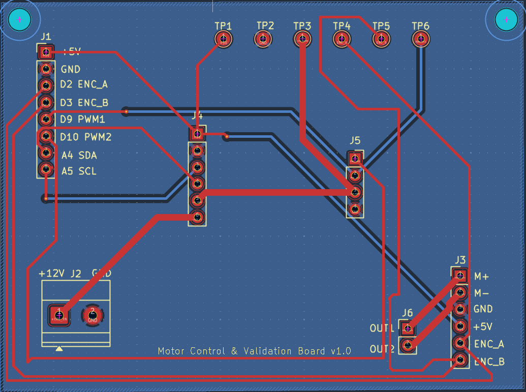
Motor validation board is an open-source printed circuit board by damian-EE, from the damian-EE/motor-control-validation-platform repository on GitHub, published under the MIT licence. It is a 2-layer board of 80 × 60 mm with 14 parts on 12 nets, routed with 71 tracks and 3 vias.
It belongs with the robots and motor control boards of this library.
A 2-layer KiCad carrier PCB for a small motor test platform (a 12 V DC gear motor with a Hall encoder), plus the breadboard prototype used to validate the circuit. The prototype drives the motor from an Arduino through an H-bridge, measures speed and supply current while it runs, and logs the data to CSV with a Python script. The PCB replaces the breadboard wiring.
time_ms,pwm,rpm,current_mA,voltage_V every 500 ms over USB serial.flowchart LR
PSU["12 V supply"] --> INA["INA219<br/>current / voltage"]
INA --> DRV["DRV8871<br/>H-bridge"]
DRV --> MOT["12 V gear motor<br/>+ Hall encoder"]
ARD["Arduino Uno R3"] -- "D9 / D10 PWM" --> DRV
MOT -- "encoder A (D2)" --> ARD
INA -- "I2C (A4 / A5)" --> ARD
ARD -- "USB serial, 9600 baud" --> PC["Python logger<br/>CSV + plots"]Hardware used
| Part | Notes |
|---|---|
| Arduino Uno R3 | Motor control, encoder counting, sensor readout |
| DRV8871 breakout | H-bridge, PWM on IN1 (D9) / IN2 (D10) |
| INA219 breakout | High-side current/voltage sensing, I2C |
| 12 V DC gear motor with Hall encoder (25GA370H type) | 45:1 gearbox, 12 pulses/rev on the encoder, 540 pulses per output revolution |
| 12 V supply | Motor and driver |
| Arduino pin | Signal | Used for |
|---|---|---|
| D9 | PWM_IN1 | DRV8871 IN1 (forward) |
| D10 | PWM_IN2 | DRV8871 IN2 (reverse) |
| D2 | ENC_A | Encoder channel A, rising-edge interrupt |
| D3 | ENC_B | Wired to the board, not read by the current firmware |
| A4 / A5 | SDA / SCL | INA219 |
| 5V / GND | Encoder and INA219 supply, common ground |
The INA219 sits in series on the high side: supply + goes to VIN+, VIN- goes to the DRV8871 VM pin.
firmware/
  motor_controller/      Final Arduino sketch (control + encoder + INA219)
  i2c_scanner/           Utility to confirm the INA219 is detected
  development/           Earlier steps: motor control only, then + encoder RPM
python_logger/
  motor_logger.py        Serial logger and automatic PWM sweep
  plot_results.py        Plots and steady-state table for one run
  compare_runs.py        Overlay and repeatability table for several runs
hardware/
  kicad/                 KiCad 10 project (schematic + PCB)
  gerbers/               Gerber and drill files (also zipped)
  schematic.pdf          Schematic
  bom.csv                Bill of materials
test_results/            Raw CSVs and steady-state summaries
media/ Plots and board images1. Firmware. In the Arduino IDE install the Adafruit INA219 library (Library Manager), open firmware/motor_controller/motor_controller.ino, select the Uno and upload. If the Serial Monitor reports Failed to find INA219 chip, upload firmware/i2c_scanner to check the wiring (the INA219 normally shows up at 0x40). Close the Serial Monitor before using the logger, since only one program can hold the port.
2. Python setup. Run all Python commands from the repository root so the outputs land in test_results/ and media/.
pip install -r python_logger/requirements.txt
python python_logger/motor_logger.py --list     # find the serial port
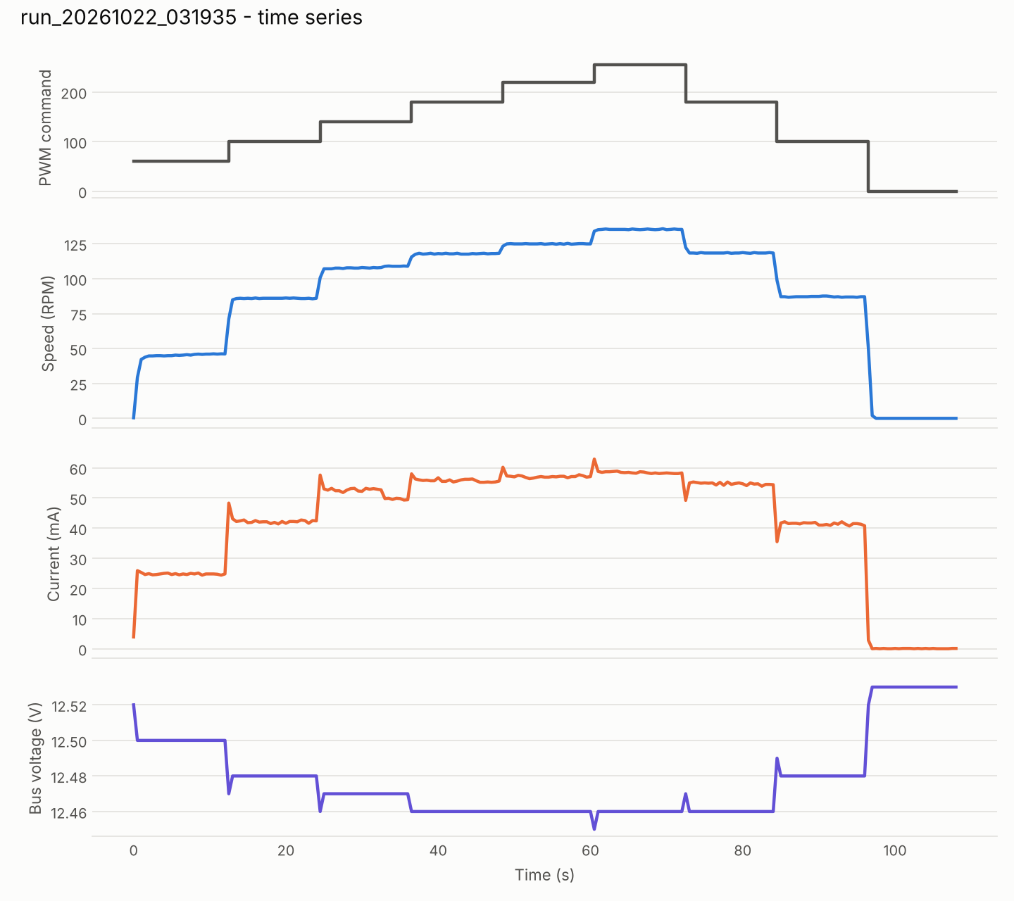
3. Run a sweep. This steps through PWM 60, 100, 140, 180, 220, 255, then back down through 180, 100, 0, holding each level for 12 s (about 108 s total) and writing test_results/run_<timestamp>.csv:
python python_logger/motor_logger.py --port COM3 --sweep --hold 12python python_logger/motor_logger.py --simulate runs the whole pipeline with a synthetic motor and no hardware. Simulated output is only for testing the software and is not real data.
4. Plot.
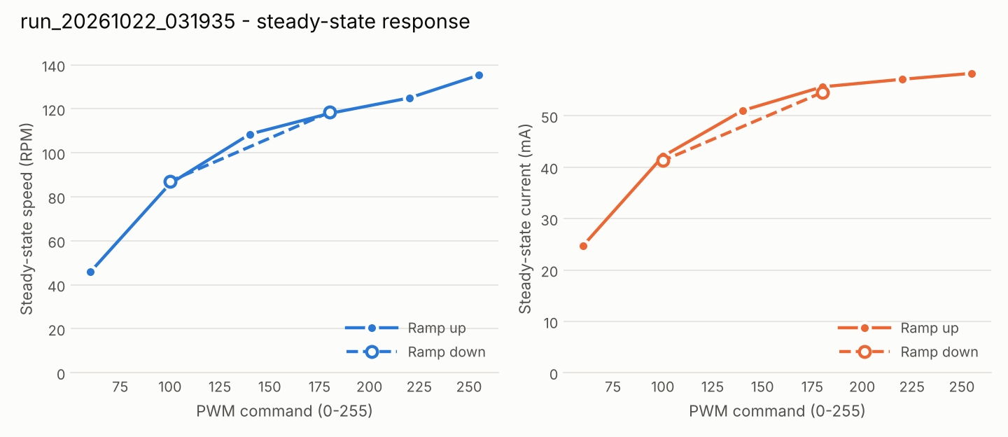
python python_logger/plot_results.py test_results/run_20261022_031935.csv
python python_logger/compare_runs.py test_results/run_20261022_030916.csv test_results/run_20261022_031231.csv test_results/run_20261022_031935.csvAll results are no-load (the motor shaft was not loaded) on a 12 V supply, from three full sweeps on 2026-10-22. Each value is the mean over the second half of a 12 s hold, so the settling transient is excluded.
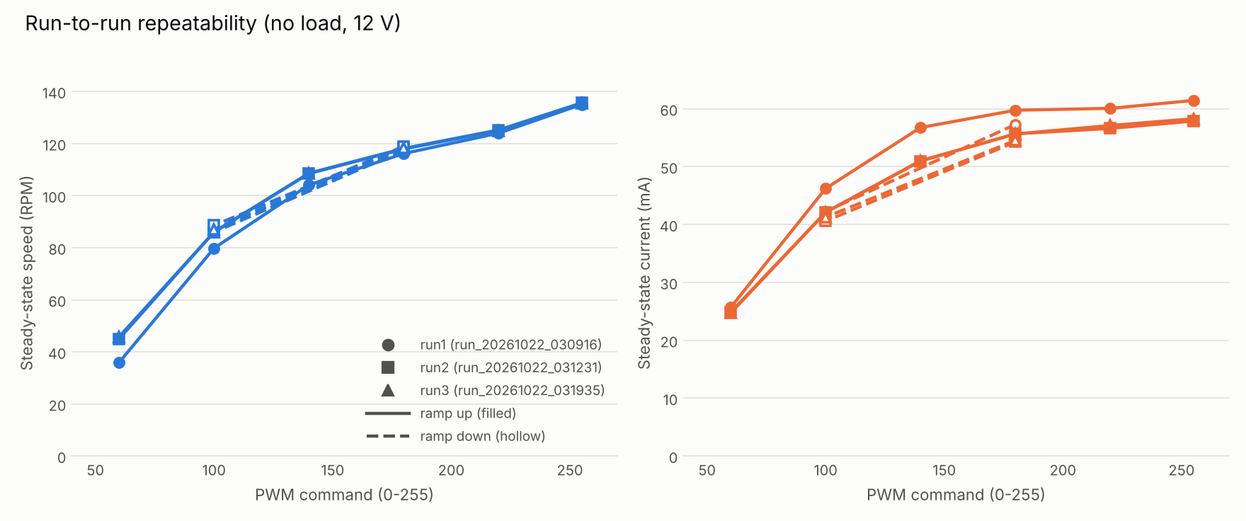
Steady-state speed on the ramp up, three runs:
| PWM | Run 1 (cold start) | Run 2 | Run 3 | Runs 2-3 differ by |
|---|---|---|---|---|
| 60 | 35.96 RPM | 45.03 | 45.80 | 1.7 % |
| 100 | 79.81 | 86.03 | 85.97 | 0.1 % |
| 140 | 104.12 | 108.62 | 108.49 | 0.1 % |
| 180 | 116.17 | 118.13 | 117.92 | 0.2 % |
| 220 | 124.00 | 125.22 | 124.95 | 0.2 % |
| 255 | 135.02 | 135.64 | 135.34 | 0.2 % |
Supply current at full PWM was about 58 mA (roughly 0.72 W electrical input) in the two warm runs and 61 mA in the cold run, and about 0.05 mA with the motor stopped. Bus voltage stayed between 12.45 V and 12.53 V in all three runs.
Time series of the third run:
Steady-state response of the third run (ramp up solid, ramp down dashed):
Raw data and per-run summaries are in test_results/, and the three-run comparison is in media/repeatability_summary.csv.
A 80 x 60 mm, 2-layer carrier board (KiCad 10.0.6) that connects the Arduino, the DRV8871 and INA219 modules, the power input and the motor/encoder connector through headers instead of breadboard wires.
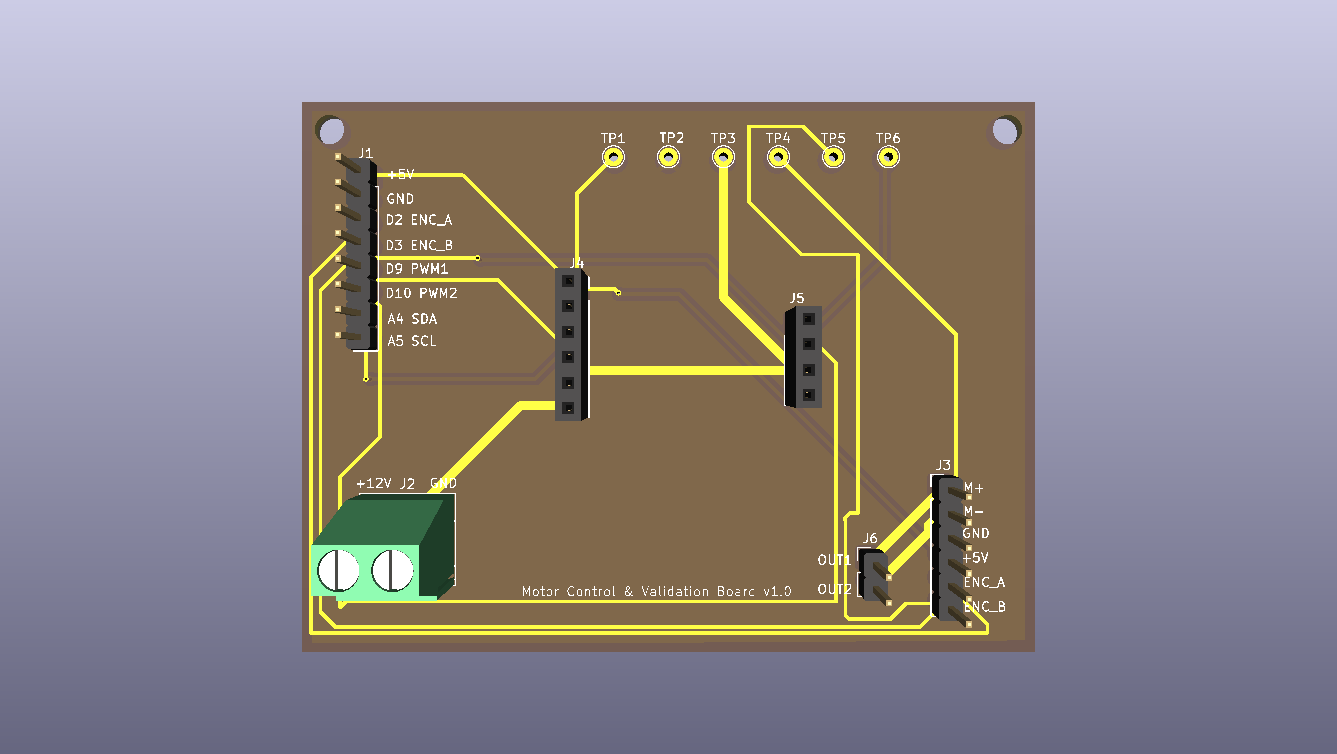
Files: hardware/schematic.pdf, hardware/bom.csv, hardware/gerbers/, hardware/kicad/.
The board is designed and passes DRC, but it has not been fabricated or tested. All measurements above were taken on a breadboard prototype with the same circuit. Before ordering the board, check that the socket pin order on J4 (INA219) and J5 (DRV8871) matches the actual breakout modules in use, since module pin orders vary between vendors.
The focus of this project is PCB design and hardware validation: the KiCad schematic and board, the breadboard prototype of the circuit, and the test runs and data shown above.
MIT, see LICENSE.
| Qty | Value | Footprint | References |
|---|---|---|---|
| 6 | TestPoint | TestPoint:TestPoint_THTPad_D2.0mm_Drill1.0mm | TP1, TP2, TP3, TP4, TP5, TP6 |
| 1 | ARDUINO_LINK | Connector_PinHeader_2.54mm:PinHeader_1x08_P2.54mm_Vertical | J1 |
| 1 | DRV8871_MODULE | Connector_PinSocket_2.54mm:PinSocket_1x04_P2.54mm_Vertical | J5 |
| 1 | DRV_OUT | Connector_PinHeader_2.54mm:PinHeader_1x02_P2.54mm_Vertical | J6 |
| 1 | INA219_MODULE | Connector_PinSocket_2.54mm:PinSocket_1x06_P2.54mm_Vertical | J4 |
| 1 | MOTOR_ENC | Connector_PinHeader_2.54mm:PinHeader_1x06_P2.54mm_Vertical | J3 |
| 1 | POWER_IN | TerminalBlock_Phoenix:TerminalBlock_Phoenix_MKDS-1,5-2-5.08_1x02_P5.08mm_Horizontal | J2 |
The 12 most common of 14 parts.
google/mozc-devices
Circuit diagrams and firmware source code for Gboard DIY keyboards


hackclub/OnBoard
💡 Join 1,000 teenagers and make your first PCB with a $100 grant!


Twotoz/C5VRX
Ultra-minimal, zero-CPU 5.8 GHz analog FPV video receiver using ESP32-C5 Wi-Fi 6 PHY MODEM_DIAG, BitScrambler WBFM demodulation & resistor DAC CVBS


It measures 80 × 60 mm and has 2 copper layers, 1.6 mm thick.
14 parts. The full list of its parts is on this page, with links to each part's symbol and footprint where PCBKit's library has them.
From the damian-EE/motor-control-validation-platform repository on GitHub, at the commit this page was made from: the board is hardware/kicad/motor-validation-board.kicad_pcb and its schematic hardware/kicad/motor-validation-board.kicad_sch. PCBKit opens the board in the browser, with nothing to install.
Its repository publishes it under the MIT licence: you may reuse it on that licence's terms (keep the author's notice, and for a copyleft licence share your changes alike).