

2 layers18.5 × 26 mm
24g2usb rp2350zero
joypad-ai/joypad-os
Universal controller firmware for building adapters, dongles, and custom controllers.
4 parts1.7kApache-2.0

 daleking/Amiga_to_VGA_Buffered15
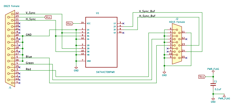
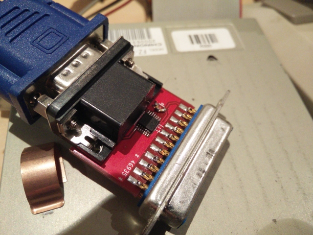
This VGA buffered adaptor uses a SN74HCT08PWR to keep the size down (and stay true to the original Commodore design). You will also need a DB23 female solder cup connector and a VGA PCB mount connector (and a capacitor).
Amiga to VGA Buffered is an open-source printed circuit board by daleking, from the daleking/Amiga_to_VGA_Buffered repository on GitHub, published under the MIT licence. It is a 2-layer board of 32.5 × 21.1 mm with 4 parts on 27 nets, routed with 123 tracks and 4 vias.
It is built around the SN74HCT08PWR. Its parts include 2 connectors, 1 capacitor and 1 IC. It belongs with the retro computing and games boards of this library.
This VGA buffered adaptor uses a SN74HCT08PWR to keep the size down (and stay true to the original Commodore design). You will also need a DB23 female solder cup connector and a VGA PCB mount connector (and a capacitor).
This is a replacement for the original 390682-01
I don't know what the other chip in the 390682-03 is, or what the diodes (protection?) are for either. Apparently this version has a fix for video toasters, so assume that this repro will behave the same and not work with video toasters either.
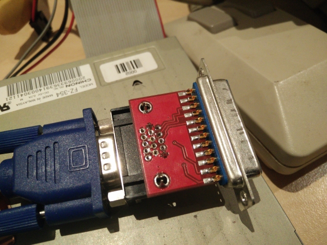
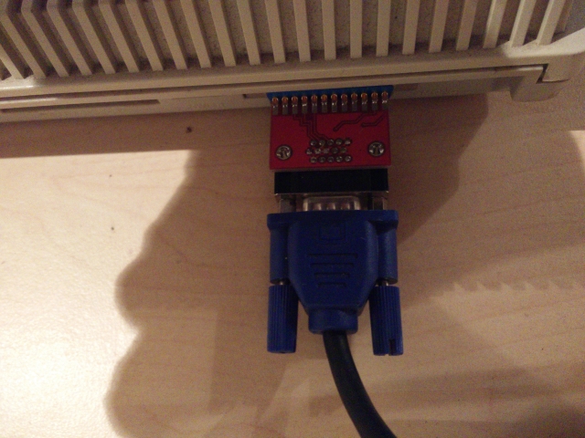
The design is upside down so that there is minimal strain on the DB23 video connector. The VGA cable lies close to flat on the table. I didn't want the weight of the cable pulling down on the connector.
No warranty, although I have built one and tested on A4000, A2000 and A500.
This method is a lot easier than stripping wires and soldering the cups :)
If you are lazy, you can order PCBs from dirtypcbs.com and using that link I get a dollar woo! If you are cheap just grab the gerber zip file and get them done wherever you like.
I suggest 1.2mm board thickness (1.6mm works but is a tight fit).
Dale
| Qty | Value | Footprint | References |
|---|---|---|---|
| 1 | 0.1uF | Capacitors_SMD:C_1206 | C1 |
| 1 | DB23 Female | conn-db23_Female_Solder_Cup:conn-db23_Female_Solder_Cup | J1 |
| 1 | HD15 Female | conn-db15-SPC15430:conn_SPC15430 | J2 |
| 1 | SN74HCT08PWR | SOP65P640X120-14N | U1 |
joypad-ai/joypad-os
Universal controller firmware for building adapters, dongles, and custom controllers.


hackclub/OnBoard
💡 Join 1,000 teenagers and make your first PCB with a $100 grant!

tardate/LittleArduinoProjects
a collection of "Little Electronic & Arduino Projects", most involving electronics or an Arduino in one way or another!

drandyhaas/KiCadRoutingTools
A set of Python/Rust tools to aid routing in KiCad

osy/XG_Mobile_Station
Open source eGPU dock for ROG Ally and ROG Flow

Luos-io/luos_engine
Open-source and real-time orchestrator for cyber-physical-systems, to easily design, test and deploy embedded applications and digital twins.

NVNTLabs/switch2-SDEX2M2
Micro SD Express to M.2 NVME Adapter for Nintendo Switch 2
It measures 32.5 × 21.1 mm and has 2 copper layers, 1.6 mm thick.
4 parts, built around the SN74HCT08PWR. The full list of its parts is on this page, with links to each part's symbol and footprint where PCBKit's library has them.
From the daleking/Amiga_to_VGA_Buffered repository on GitHub, at the commit this page was made from: the board is Amiga_to_VGA_Buffered.kicad_pcb. PCBKit opens the board in the browser, with nothing to install.
Its repository publishes it under the MIT licence: you may reuse it on that licence's terms (keep the author's notice, and for a copyleft licence share your changes alike).