
2 layers52.2 × 52.2 mm
Base promicro
google/mozc-devices
Circuit diagrams and firmware source code for Gboard DIY keyboards
30 parts3kApache-2.0

 cyfdecyf/c-dux3
A split keyboard PCB designed with Ergogen v4.
C dux is an open-source printed circuit board by cyfdecyf, from the cyfdecyf/c-dux repository on GitHub, published under the MIT licence. It is a 2-layer board of 154.4 × 112.7 mm with 30 parts on 54 nets, routed with 152 tracks and 19 vias.
It belongs with the keyboards and input boards of this library.
| C. Dux front | C. Dux back |
|---|---|
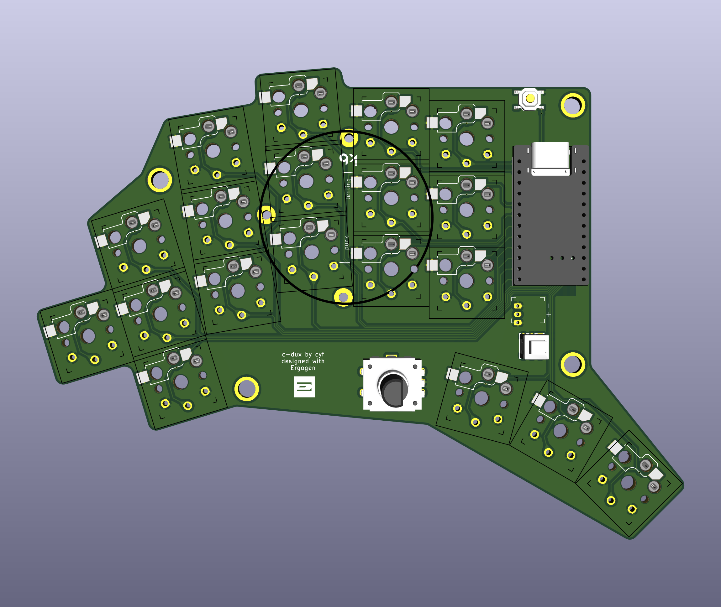 | 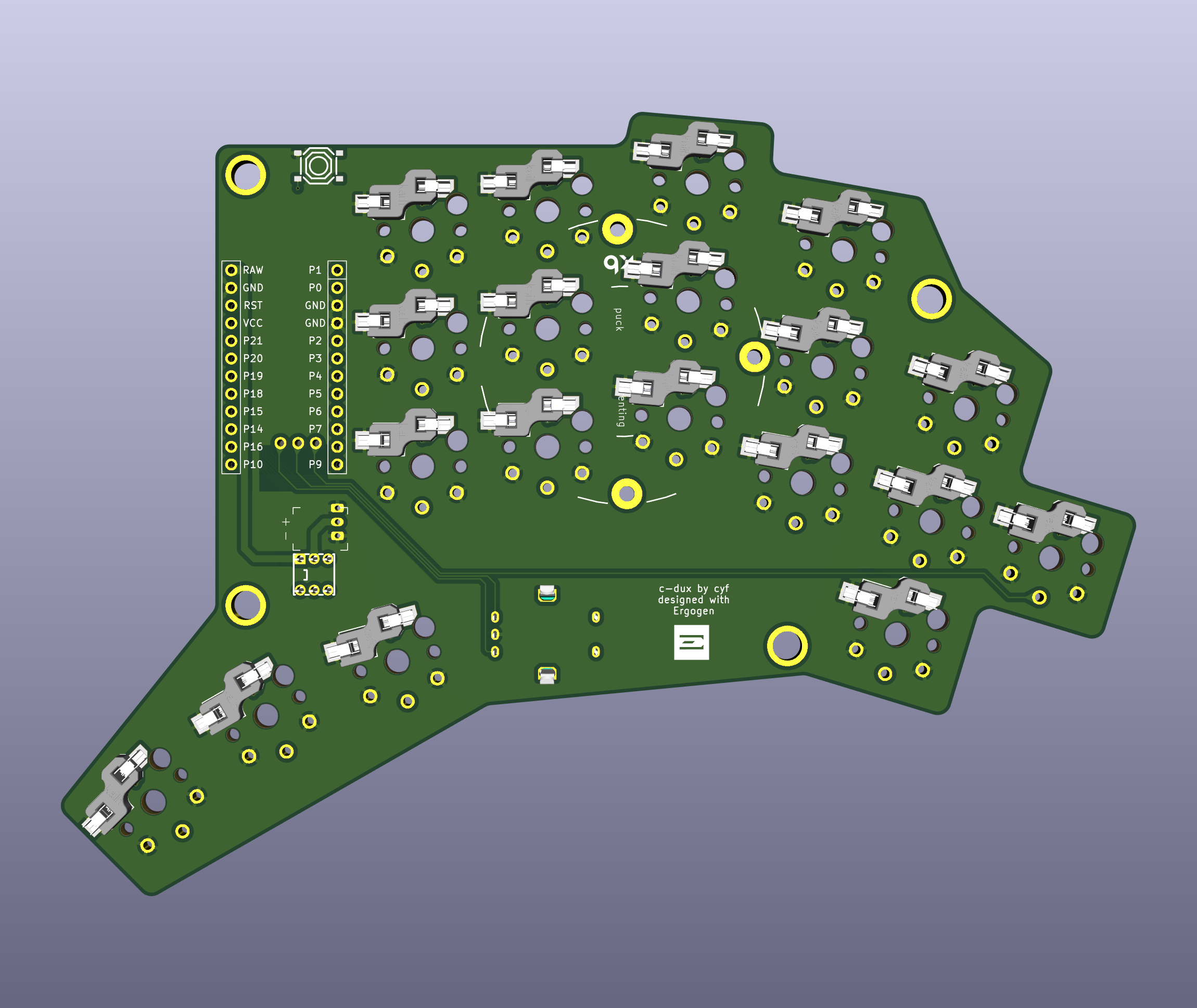 |
C. Dux is a 38-key split wireless keyboard inspired by rae-dux and Architeuthis Dux (A. Dux).
Note: I did not consider designing a case when I designed the PCB, as I use the keyboard with naked PCB. A 3D printed vertical stand came later, see 3D printed case below. So it's better to use leadless PCB and solder. I find SAC305 solder (with 380-degree solder iron) is a little harder to use compared to Tin-Lead 63/37 solder (with 280-degree solder iron), but not too much.
The keyboard layout and PCB is generated using Ergogen v4. Traces are added manually in KiCAD 8. I learned how to use Ergogen form FlatFootFox's Let's Design A Keyboard With Ergogen v4 series articles, highly recommended!
Refer to my zmk-config repo. I do local build, github workflow is not tested.
Some combos are inspired by Glove80 TailorKey. (I own one Moergo's Glove80. It's a great keyboard. I started using home-row mod with Glove80.)
Here's v2.0 PCB gerbers file. You can download the file and place order from JLC. I made a few fixes for problems found after I got the PCB from JLC, so it's not exactly the same file I've used but should work without problems.
For non-key footprints (power/reset switches, etc.), my workflow is:
As I suffer from RSI, I choose the 20g pink Choc v1 switches (which is the lightest switches I know). For keycaps, I find the 3D printed saddle variant of KLP-Lame-Keycaps quite pleasant to use. The keycap curve makes it easy to press the up & down rows, and helps a lot to position fingers on the home row.
PCBs are ordered from JLC. Power and reset switch are from LCSC.
I got the idea of mouting keyboard on desk and let hands go twards the ground from Ben Vallack's video The Perfect TENTING SOLUTION For Split Keyboards. Check out Ben Vallack's channel if you are interested in ergonomic keyboards.
This is the most comfortable way for me to use a keyboard. This position helps a lot to relieve my RSI and I can work all day long without much pain in my forearm.
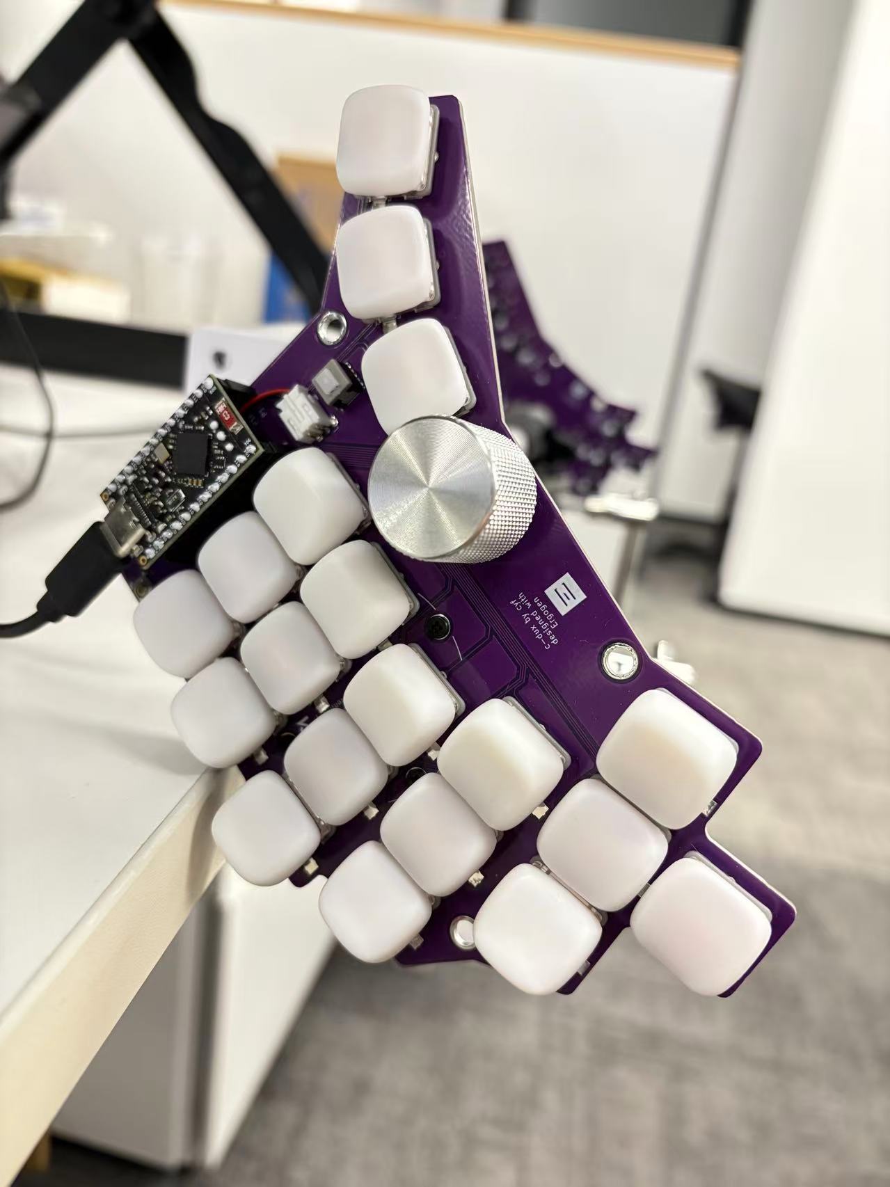
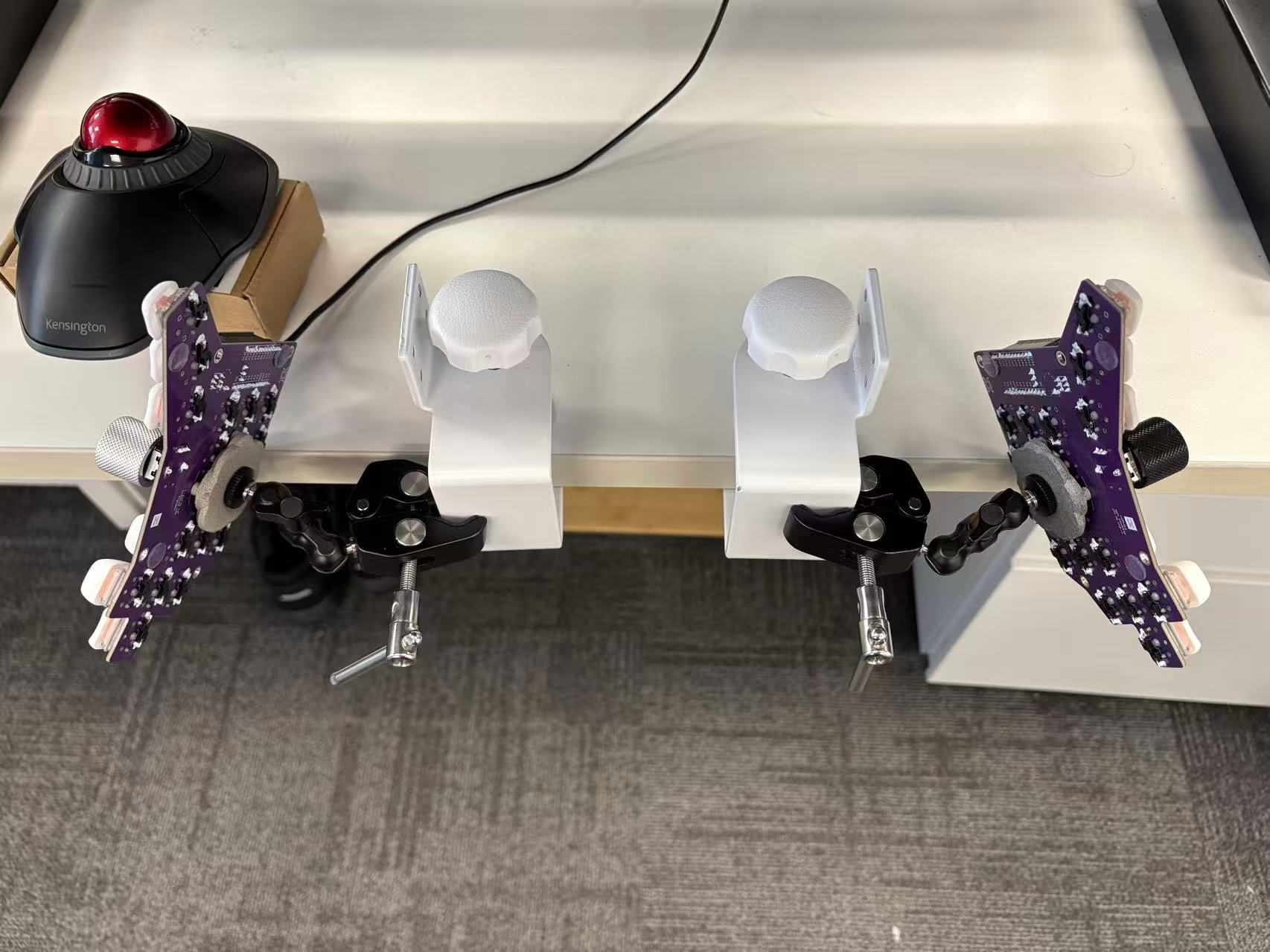
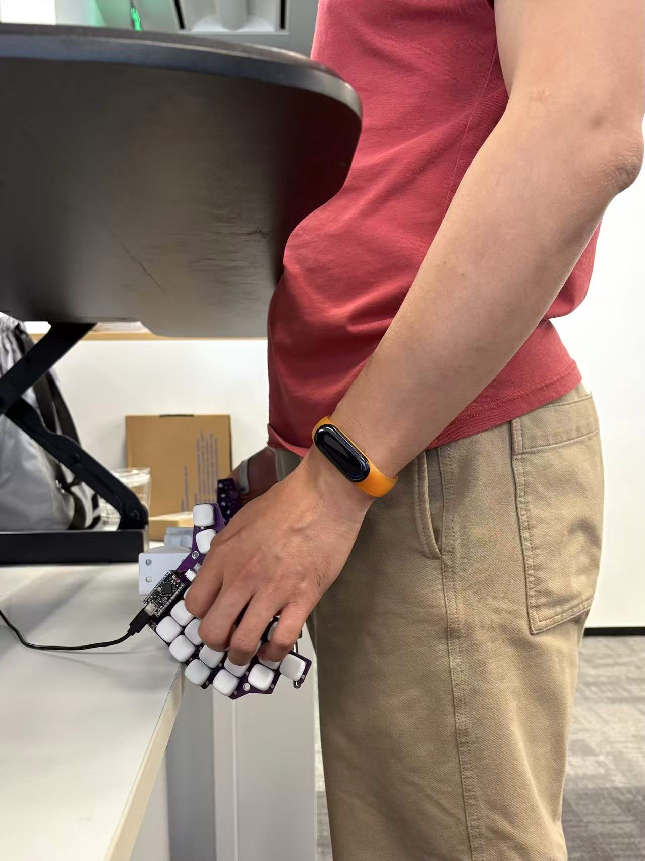
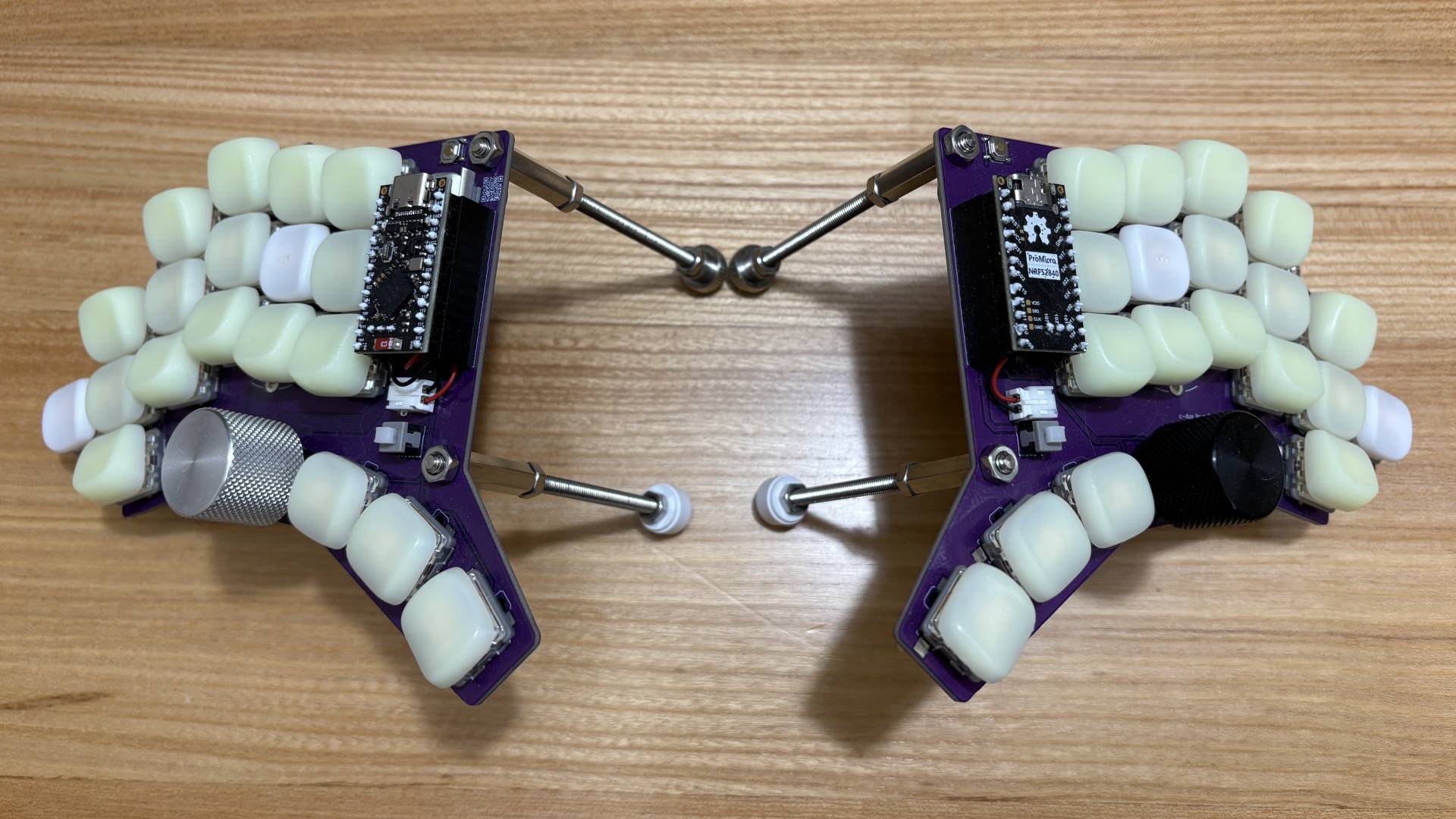
The keyboard stands vertically on the desk with a 3D printed case, designed with build123d. It is a two-piece design: a shared base (symmetric, printed once) plus an upright that sets the recline angle. The two parts join with tongue-and-groove keys and 2×M4 screws from the bottom, so trying a different recline angle only requires reprinting the upright.
This is my first attempt to build a keyboard. The rotary encoder is difficult to reach which is the biggest mistake I made.
The keycap used in this version is Chosfox's CFX keycap. (Search for "哈狐 Chosfox" on Taobao if you live in China.) This keycap is not as smootch as Moergo's MCC keycap, but it's still quite good and is much cheaper. But as I like the curved keywell of Glove80, I switched to KLP Lame keycaps later.
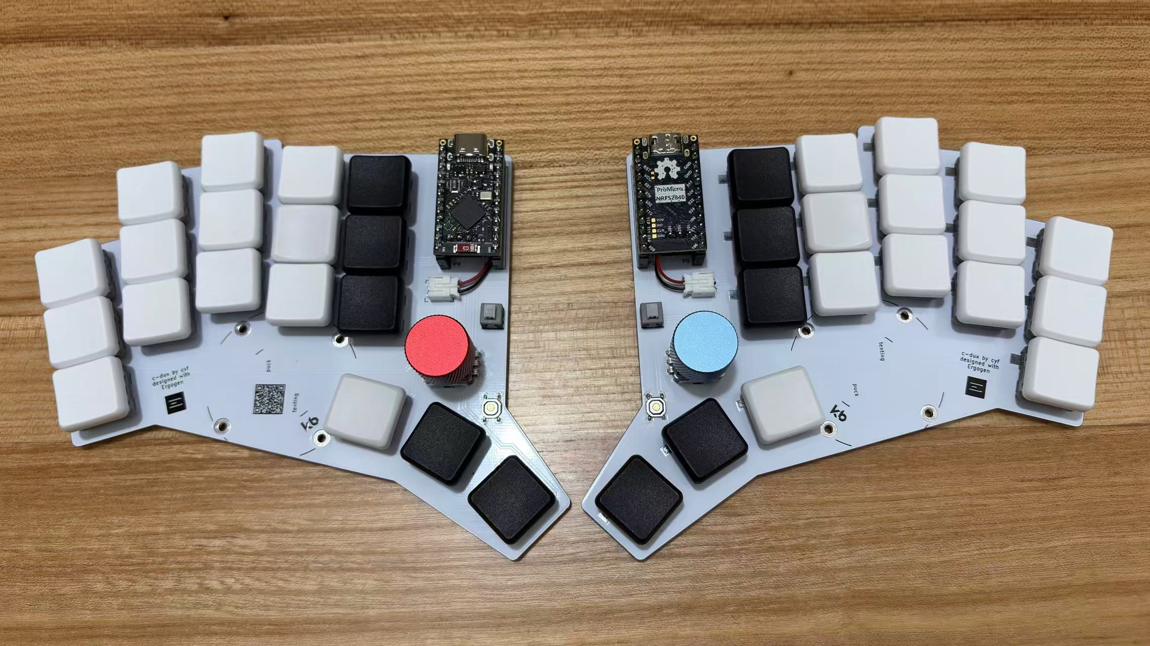
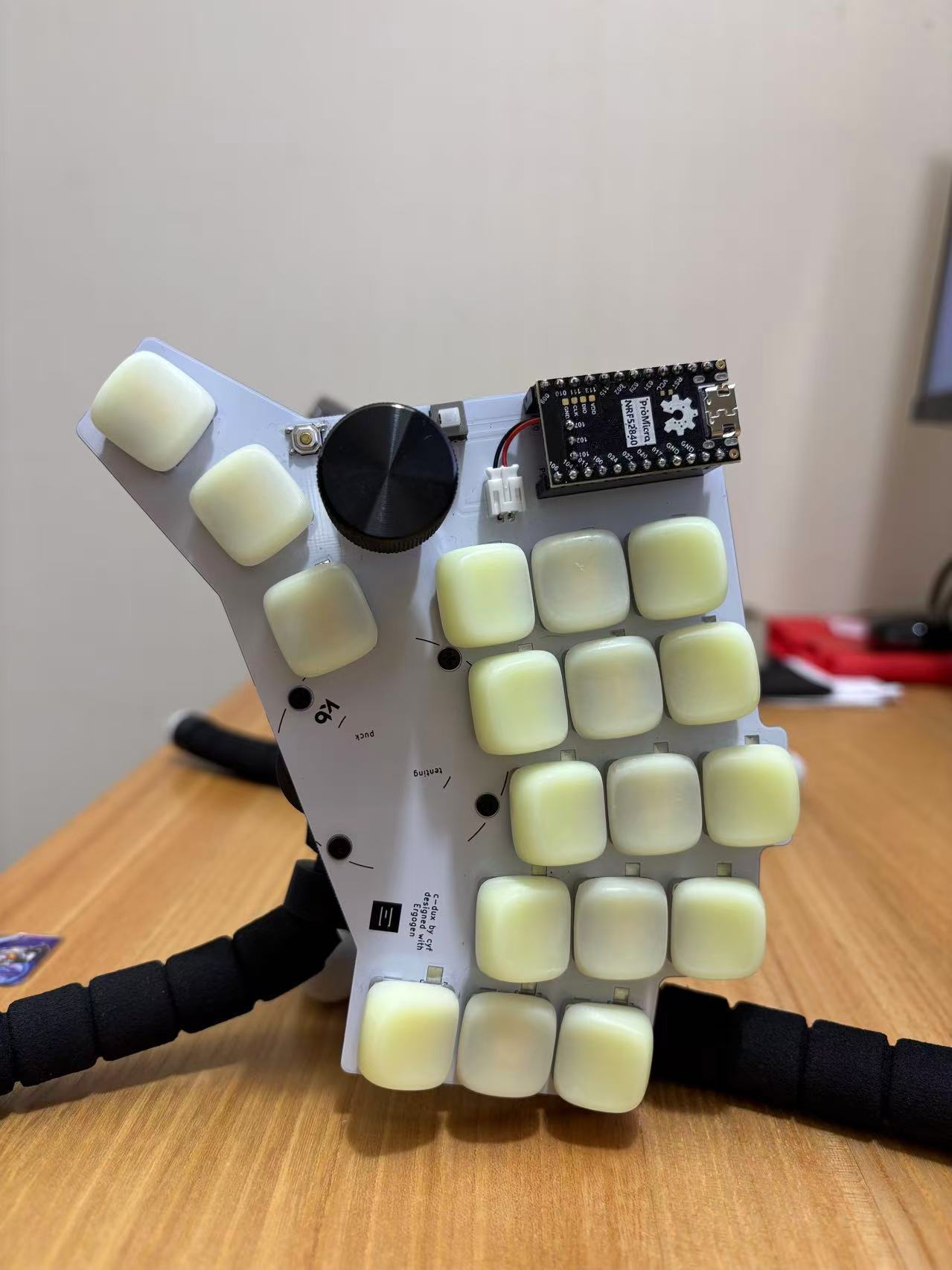
I'm quite comfortable with C. Dux v2 and I'm not planning to build an improved version soon. But I do plan to build a third keyboard for backup.
Here are a few things that I'd like to change:
| Qty | Value | Footprint | References |
|---|---|---|---|
| 19 | — | ceoloide:switch_choc_v1_v2 | S1, S2, S3, S4, S5, S6, S10, S11, S12, S13, S14, S15, S16, S17, S18, S19 +3 |
| 4 | — | ceoloide:mounting_hole_plated | H1, H2, H3, H4 |
| 1 | SW-SMD_4P | easyeda2kicad:SW-SMD_4P-L5.1-W5.1-P3.70-LS6.5-TL_H1.5 | SW2 |
| 1 | SW_Push_Lock | easyeda2kicad:SW-TH_5.8ZSPT | SW1 |
| 1 | Tenting Puck, no hole | TentingPuck_NoHole | TP1 |
| 1 | — | ceoloide:mcu_supermini_nrf52840 | MCU1 |
| 1 | — | ceoloide:battery_connector_jst_ph_2 | JST1 |
| 1 | — | ceoloide:utility_ergogen_logo | LOGO1 |
| 1 | — | ceoloide:rotary_encoder_ec11_ec12 | RE1 |
google/mozc-devices
Circuit diagrams and firmware source code for Gboard DIY keyboards


VoronDesign/Voron-Hardware
Cool Hardware designed by the Voron Design group

hoglet67/RGBtoHDMI
Bare-metal Raspberry Pi project that provides pixel-perfect sampling of Retro Computer RGB/YUV video and conversion to HDMI

tenderlove/initial-v
It's a BMW shifter converted to a Bluetooth Keyboard that you use with Vim

hackclub/OnBoard
💡 Join 1,000 teenagers and make your first PCB with a $100 grant!


It measures 154.4 × 112.7 mm and has 2 copper layers, 1.6 mm thick.
30 parts. The full list of its parts is on this page, with links to each part's symbol and footprint where PCBKit's library has them.
From the cyfdecyf/c-dux repository on GitHub, at the commit this page was made from: the board is pcb/v2.0/c-dux.kicad_pcb. PCBKit opens the board in the browser, with nothing to install.
Its repository publishes it under the MIT licence: you may reuse it on that licence's terms (keep the author's notice, and for a copyleft licence share your changes alike).