Skip to the content
2 layers100 × 40 mmWorkshop project, the printed circuit board in 3D

an interactive kicad workshop for diy video-art making instruments

Size
100 × 40 mm
Copper layers
2
Thickness
1.6 mm
Parts
30
Nets
28
Pads
100
Tracks, vias
114, 0
Pours
2
Routed
Yes
KiCad
KiCad 5 (file 20171130)
Created
27 Oct 2020
Updated
19 Jul 2021

Overview

Workshop project is an open-source printed circuit board by cyberboy666, from the cyberboy666/kicad_video_workshop repository on GitHub, published under the GPL-3.0 licence. It is a 2-layer board of 100 × 40 mm with 30 parts on 28 nets, routed with 114 tracks and 0 vias.

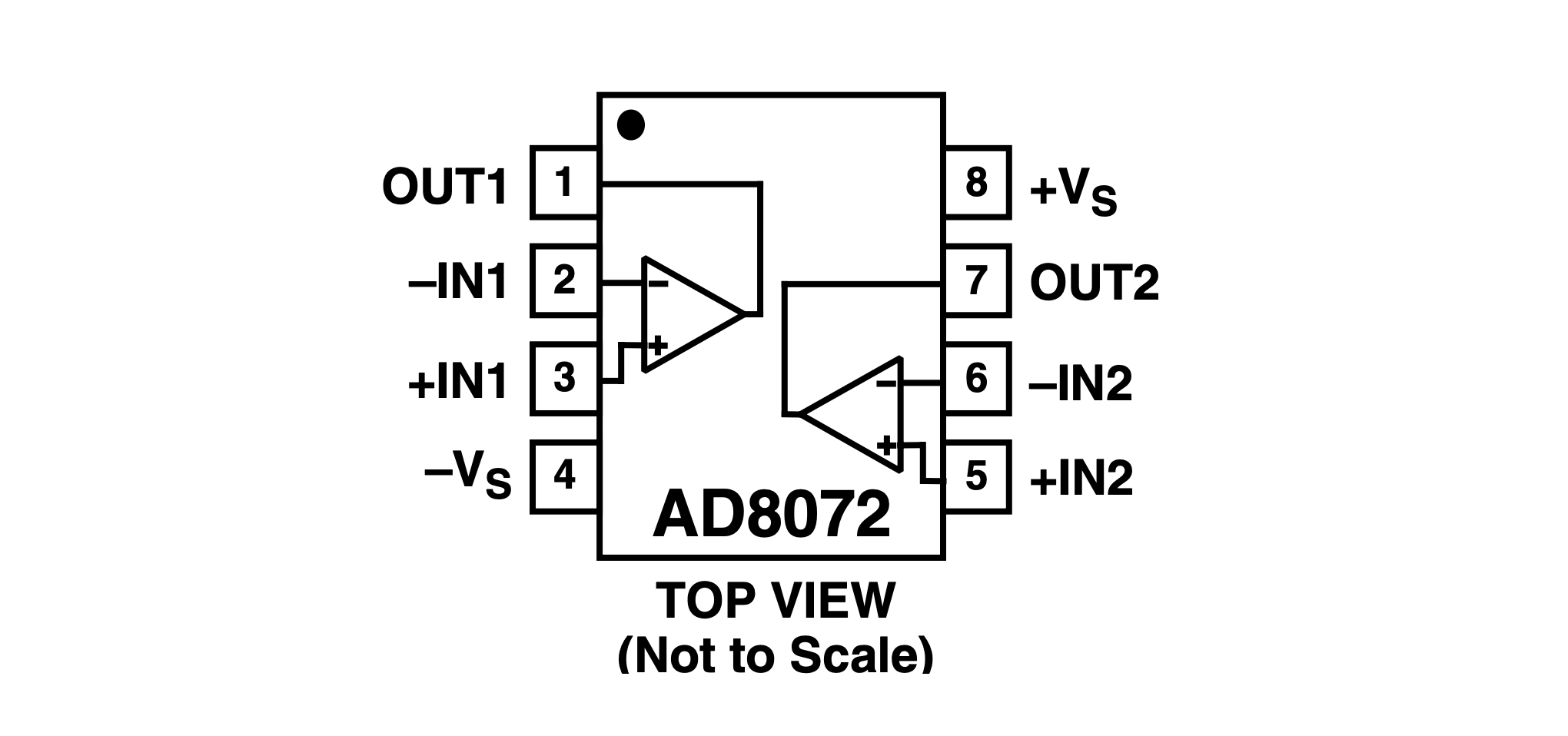
It is built around the AD8072JN. Its parts include 8 capacitors, 7 switches, 3 connectors, 2 resistors and 2 ICs.

Main components

1

README

README.md

kicad_video_workshop

an interactive kicad workshop for diy video-art making instruments

getting started:

  • download kicad ( version >=5 )
  • download this repo (git clone or as zip under code here)
  • open the file in workshop_project / workshop_project.pro with kicad

the challenge:

together we will try to adapt a video glitch processing circuit created orginally by Karl Klomp known as the rupter. this project and many other interesting historic video hardware glitch machines can be seen on web-archive of their site.

details of the original circuit

original circuit:

image

image

image

image

image

my interpretation:

there are a few quirks of this design that make it difficult to adapt to a pcb project:

  • its not clear which pot values to use - 100k or 1k ? (100ohm pots are bery uncommon) after testing i liked the effects with 1k_pots better
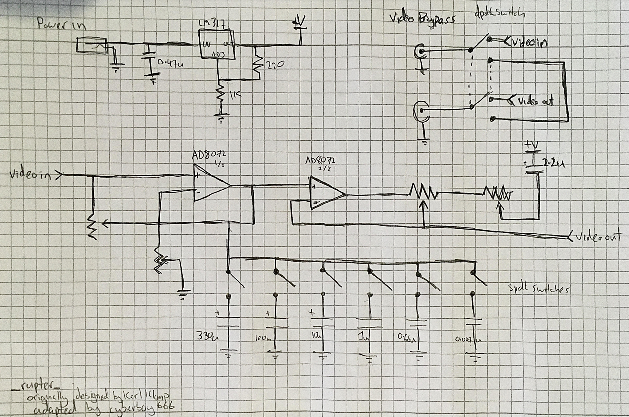
  • although possible to use a rotary switch on pcb, the footprints for these are a little complicated and i opted to use some (cheap) slide switches in parallel instead. lower resistor values seemed to work better here than higher ones. you should experiment for yourself which values to use here !
  • a 'circuit bent' style schematic can be difficult to understand since often are based on misusing components. Bastien made a simulation of the first stage which doesnt appear to do much in theory. as is often the case things will be different in practice.

further notes on the circuit

from building:

  • tried skipping the power regulator part and going 5v straight into the ic -> seems to work quite well
  • lm317 is adjustable voltage regulator - ouput voltage is 1.25*(1 + r2/r1) where in this case r2=1k and r1=220ohm. so voltage output should be around 7v. confirmed this when building
  • i measured the current from the lm317 and was around 20mA so could also use the smaller/cheaper part
  • tried with 200ohm , 1k and 100k pots. all were quite interesting. i would choose 1k pots myself.
  • tried with some different cap values. no cap connected gives closer to a clean signal. higher caps tend to just give dropouts (with a few hard to tune effects) lower values seems most interesting. i would experiment some more with which cap values to use.
  • i tried to figure out which way to orieintate the pots to make most sense. still it is not that obvious to me. would have to play around with the circuit some more to fine tune this.
  • i tried switching -in/out of second opamp to see if liked the effect better but it wasnt as interesting.
  • i tested with ntsc and it seems to give better colour glitches than as i remember with pal

the schematic

here is a handdrawn schematic of my interpretation which we will try to create in kicad:

image

some kicad shortcuts

Schematics shortcuts:

  • a to add symbol
  • m to move symbol
  • e to edit symbol
  • c to duplicate symbol
  • w to draw wire
  • esc to return to pointer tool

pcb_route shortcuts:

  • m to move item
  • x to route track
  • v to add via
  • esc to return to pointer tool

links to parts used:

partfootprintlink
rca_jack-mouser, ali
spdt_slide_switch-tayda
spdt_toggle_switch-tayda
dpst_slide_switch-tayda
dpst_toggle_switch-tayda
ad8072-mouser_dip
1k_pot-tayda, mouser
7pst_rotary_switchnonetayda, mouser

Parts

30
QtyValueFootprintReferences
6SW_SPDTlib_fp:spdt_slide_switch_small_taydaSW2, SW3, SW4, SW5, SW6, SW7
41k_potlib_fp:pot_vertical_9mmRV1, RV2, RV3, RV4
2rcalib_fp:rca_verticalJ1, J3
10.047ufCapacitor_THT:C_Disc_D4.7mm_W2.5mm_P5.00mmC8
10.1ufCapacitor_THT:C_Disc_D4.7mm_W2.5mm_P5.00mmC7
10.47uCapacitor_THT:CP_Radial_D5.0mm_P2.50mmC1
10.68ufCapacitor_THT:C_Disc_D4.7mm_W2.5mm_P5.00mmC6
1100ufCapacitor_THT:CP_Radial_D5.0mm_P2.50mmC3
11kResistor_THT:R_Axial_DIN0204_L3.6mm_D1.6mm_P5.08mm_HorizontalR2
11ufCapacitor_THT:C_Disc_D4.7mm_W2.5mm_P5.00mmC5
12.2ufCapacitor_THT:CP_Radial_D5.0mm_P2.50mmC4
1220Resistor_THT:R_Axial_DIN0204_L3.6mm_D1.6mm_P5.08mm_HorizontalR1
1330ufCapacitor_THT:CP_Radial_D5.0mm_P2.50mmC2
1AD8072Package_DIP:DIP-8_W7.62mm_LongPadsU2
1Barrel_Jack_Switchlib_fp:BarrelJack_HorizontalJ2
1LM317_3PinPackagePackage_TO_SOT_THT:TO-92L_HandSolderU1
1SW_DPDT_x2lib_fp:dpdt_mini_toggle_switch_taydaSW1

The 26 most common of 30 parts.

More from cyberboy666/kicad_video_workshop

2
  • 2 layers50 × 30 mmDemo project, the printed circuit board in 3D

    Demo project

    cyberboy666/kicad_video_workshop

    an interactive kicad workshop for diy video-art making instruments

    6 parts3GPL-3.0
  • 2 layers50 × 50 mmDemo project complete, the printed circuit board in 3D

    Demo project complete

    cyberboy666/kicad_video_workshop

    an interactive kicad workshop for diy video-art making instruments

    6 parts3GPL-3.0

Similar boards

  • 2 layers100 × 100 mmSync ope, the printed circuit board in 3D

    Sync ope

    cyberboy666/sync_ope

    effect send + sync restoring circuit - adapted from a gael jaton design

    78 parts52
  • 2 layers100 × 40 mmRupture, the printed circuit board in 3D

    Rupture

    cyberboy666/_rupture_

    simple analog video glitch circuit - adapted from a karl klomp design

    32 parts42GPL-3.0
  • 2 layers52.2 × 52.2 mmBase promicro, the printed circuit board in 3D

    Base promicro

    google/mozc-devices

    Circuit diagrams and firmware source code for Gboard DIY keyboards

    30 parts3kApache-2.0
  • 2 layers40.6 × 15.2 mmVr mmm, the printed circuit board in 3D

    Vr mmm

    rusefi/rusefi

    rusefi - GPL internal combustion engine control unit

    30 parts1.2k
  • 2 layers270 × 11 mmDaylight, the printed circuit board in 3D

    Daylight

    VoronDesign/Voron-Hardware

    Cool Hardware designed by the Voron Design group

    30 parts1.1kGPL-3.0
  • 2 layers65 × 30 mmRgb to hdmi, the printed circuit board in 3D

    Rgb to hdmi

    hoglet67/RGBtoHDMI

    Bare-metal Raspberry Pi project that provides pixel-perfect sampling of Retro Computer RGB/YUV video and conversion to HDMI

    30 parts1kGPL-3.0
  • 2 layers40.5 × 58 mmInitial v, the printed circuit board in 3D

    Initial v

    tenderlove/initial-v

    It's a BMW shifter converted to a Bluetooth Keyboard that you use with Vim

    30 parts1kApache-2.0
  • 2 layers34.3 × 41.8 mmMotionCubeViewAllForces, the printed circuit board in 3D

    MotionCubeViewAllForces

    hackclub/OnBoard

    💡 Join 1,000 teenagers and make your first PCB with a $100 grant!

    30 parts915

Questions

How big is the Workshop project PCB?

It measures 100 × 40 mm and has 2 copper layers, 1.6 mm thick.

What parts does the Workshop project use?

30 parts, built around the AD8072JN. The full list of its parts is on this page, with links to each part's symbol and footprint where PCBKit's library has them.

Where can I download the Workshop project KiCad files?

From the cyberboy666/kicad_video_workshop repository on GitHub, at the commit this page was made from: the board is workshop_project_complete/workshop_project.kicad_pcb. PCBKit opens the board in the browser, with nothing to install.

Can I use the Workshop project design in my own project?

Its repository publishes it under the GPL-3.0 licence: you may reuse it on that licence's terms (keep the author's notice, and for a copyleft licence share your changes alike).