4 layers40 × 100 mm
Integrated 1
Cuprum77/LCD_Driver
FPGA based LCD driver for cheap ST7701S displays
133 parts2CERN-OHL-S-2.0

 Cuprum77/LCD_Driver2
FPGA based LCD driver for cheap ST7701S displays
Integrated is an open-source printed circuit board by Cuprum77, from the Cuprum77/LCD_Driver repository on GitHub, published under the CERN-OHL-S-2.0 licence. It is a 4-layer board of 40 × 50 mm with 84 parts on 174 nets, routed with 1,121 tracks and 187 vias.
It is built around the RP2040, NC7SZ125M5X and AP5725WG, with the XLH335200.000000I, BAS16XV2T1G-FS and USB4105-GF-A-120 among its other parts. Its parts include 32 capacitors, 21 resistors, 10 ICs, 4 diodes and 3 connectors. It belongs with the lEDs and displays boards and the RP2040 and FPGA and CPLD boards of this library.


This design features a nasty error where the internal and IO power rails were accidentally swapped. Do not reproduce this design. A new revision is in the works.
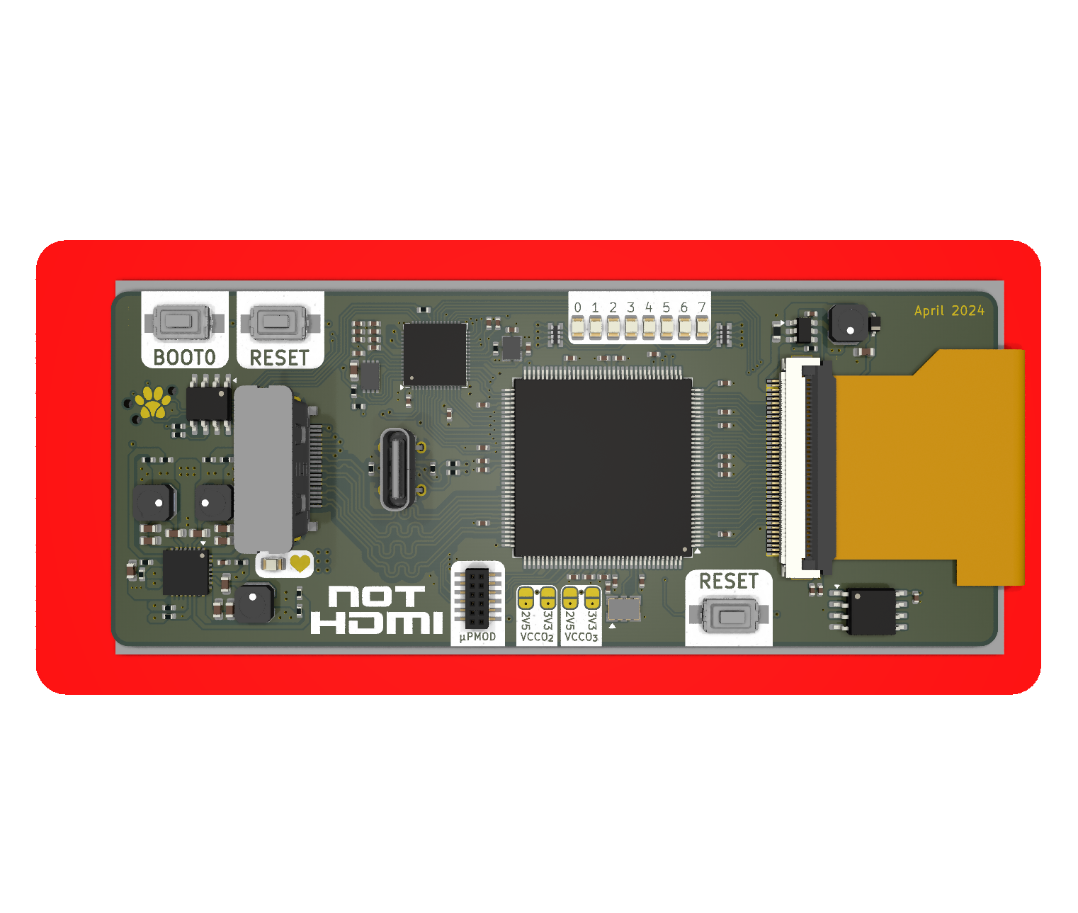
This is a PCB that integrates everything needed to drive the display. It is designed to sit on the back of the display without interfering with the display frame. It is specifically designed for the pinout of the newer non-standard displays that have come out of China in the recent years. Specifically those that support the RGB666 interface.
This design utilizes a Spartan 6 FPGA to drive the display. This was chosen over dedicated ASICs due to cost and adaptability. This should allow me to add features such as a splash screen or other custom features that are not possible with a dedicated ASIC.
The LCD connector itself is a ZIF 40 pin 0.5mm pitch connector. The following pinout is in use, with some pins being possible to reconfigure in the FPGA:
TO BE ADDED
XC6SLX9-TQG144 ↩
The DVI input is over a HDMI-like connector. This is due to licensing issues with the HDMI standard that I cannot afford to pay for. Any reference to HDMI in this project is purely for the sake of simplicity and is not meant to imply that this project is HDMI compatible. ↩
Does not support PD. ↩
Limited to USB 1.1 speeds. This is limited by the RP2040 which handles the USB interface. ↩
| Qty | Value | Footprint | References |
|---|---|---|---|
| 14 | 100n | KiCAD Library:C_0402_1005Metric | C3, C9, C13, C20, C21, C23, C25, C26, C36, C38, C41, C42, C43, C49 |
| 9 | 1u | KiCAD Library:C_0402_1005Metric | C2, C4, C5, C7, C12, C14, C40, C48, C50 |
| 5 | 1k | KiCAD Library:R_0402_1005Metric | R9, R11, R15, R18, R19 |
| 3 | 470k | KiCAD Library:R_0402_1005Metric | R4, R5, R6 |
| 3 | DNF | KiCAD Library:PTS636 SM25J SMTR LFS | SW1, SW2, SW3 |
| 3 | LOGO | LOGO | G***, G***, G*** |
| 2 | 22u | KiCAD Library:C_0603_1608Metric | C11, C17 |
| 2 | 27 | KiCAD Library:R_0402_1005Metric | R16, R17 |
| 2 | 270 | KiCAD Library:R_0402_1005Metric | R10, R20 |
| 2 | 2u2 | KiCAD Library:C_0402_1005Metric | C27, C37 |
| 2 | 5k1 | KiCAD Library:R_0402_1005Metric | R1, R3 |
| 2 | 8p | KiCAD Library:C_0402_1005Metric | C34, C35 |
| 2 | LED | KiCAD Library:D_0805_2012Metric | D2, D3 |
| 2 | SolderJumper_3_Open | Jumper:SolderJumper-3_P1.3mm_Open_RoundedPad1.0x1.5mm | JP2, JP3 |
| 2 | TestPoint | TestPoint:TestPoint_Pad_D1.0mm | TP1, TP2 |
| 2 | W25Q16JV | KiCAD Library:W25Q16JVUXIQ TR | U6, U7 |
| 1 | 100 | KiCAD Library:R_0402_1005Metric | R21 |
| 1 | 100k | KiCAD Library:R_0402_1005Metric | R7 |
| 1 | 10n | KiCAD Library:C_0402_1005Metric | C19 |
| 1 | 12MHz | KiCAD Library:ECS120836CKMTR3 | Y1 |
| 1 | 12R5 | KiCAD Library:R_0603_1608Metric | R22 |
| 1 | 1K | KiCAD Library:R_0402_1005Metric | R13 |
| 1 | 1M | KiCAD Library:R_0402_1005Metric | R2 |
| 1 | 1n 250V | KiCAD Library:C_0603_1608Metric | C1 |
| 1 | 1u | KiCAD Library:C_0603_1608Metric | C51 |
| 1 | 22u | KiCAD Library:XRNR4012 | L1 |
| 1 | 27k | KiCAD Library:R_0402_1005Metric | R8 |
| 1 | AP5725 | Package_TO_SOT_SMD:SOT-23-6 | U10 |
| 1 | BAS16XV2T1G | Diode_SMD:D_SOD-523 | D1 |
| 1 | BL | Jumper:SolderJumper-3_P1.3mm_Bridged12_RoundedPad1.0x1.5mm | JP1 |
| 1 | DEBUG | Paw-Connect:Paw-Connect_RevB_TC2030-IDC-NL_2x03_P1.27mm_Vertical | J2 |
| 1 | DNF | KiCAD Library:R_0402_1005Metric | R14 |
| 1 | FT2404A | Package_TO_SOT_SMD:SOT-23-5 | U11 |
| 1 | HDMI_A_1.4 | KiCAD Library:MOLEX_476591102 | J3 |
| 1 | NC7SZ125M5X | Package_TO_SOT_SMD:SOT-23-5 | U5 |
| 1 | RP2040 | Package_DFN_QFN:QFN-56-1EP_7x7mm_P0.4mm_EP3.2x3.2mm | U8 |
| 1 | ST7701_IPS_3.99_TOUCH | KiCAD Library:GCT_FFC2B35-40-G_REVA2_INV | DS1 |
| 1 | TLV76701DRVx | Package_SON:WSON-6-1EP_2x2mm_P0.65mm_EP1x1.6mm_ThermalVias | U3 |
| 1 | TLV76733DRVx | Package_SON:WSON-6-1EP_2x2mm_P0.65mm_EP1x1.6mm_ThermalVias | U1 |
| 1 | USB4105-GF-A-120 | KiCAD Library:CONN_217182-0001_MOL | J1 |
| 1 | XC6SLX9-TQG144 | Package_QFP:TQFP-144_20x20mm_P0.5mm | U2 |
| 1 | XLH335200.000000I | KiCAD Library:XLH335200.000000I | U4 |
| 1 | ZLLS400TA | Diode_SMD:D_SOD-323 | D4 |
It measures 40 × 50 mm and has 4 copper layers, 1.6 mm thick.
84 parts, built around the RP2040, NC7SZ125M5X, AP5725WG and XLH335200.000000I. The full list of its parts is on this page, with links to each part's symbol and footprint where PCBKit's library has them.
From the Cuprum77/LCD_Driver repository on GitHub, at the commit this page was made from: the board is hardware/integrated_1_1/integrated.kicad_pcb and its schematic hardware/Breakout_1/Breakout_1.kicad_sch. PCBKit opens the board in the browser, with nothing to install.
Its repository publishes it under the CERN-OHL-S-2.0 licence: you may reuse it on that licence's terms (keep the author's notice, and for a copyleft licence share your changes alike).
Cuprum77/LCD_Driver
FPGA based LCD driver for cheap ST7701S displays

Cuprum77/LCD_Driver
FPGA based LCD driver for cheap ST7701S displays


johonkanen/ac_psu_kicad
test full kicad conversion of latest ac_psu hardware files done by claude. originally drawn in proteus


JakobThiessen/NixieClock
Wichtig: Ohne Änderung tut die SD karte nicht. (Betrifft nur V2.0 in der V2.1 sind die Änderung im Layout schon umgesetzt)

ReuvenSwirsky/weikeypad
Modifiy Weigand Keystroke Information from Keypad so it looks like card reader to door controller