Firmware ESP32 (ESP-IDF) para programar e configurar módulos de rádio LoRa, expondo a configuração através de um servidor HTTP em Wi-Fi (SoftAP/STA), acessível também via mDNS (http:// .local/).
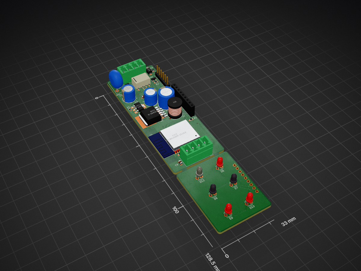
Encoder is an open-source printed circuit board by cukier, from the cukier/LoraProgrammer repository on GitHub, published under the MIT licence. It is a 2-layer board of 33 × 128.5 mm with 84 parts on 87 nets, routed with 575 tracks and 58 vias.
It is built around the ESP32-WROOM-32, LM2596S-5.0 and SP3485EN-Y, with the BC807, MMBF170 and MMBT2222ALT1G-CN among its other parts. Its parts include 35 resistors, 15 transistors, 12 diodes, 9 capacitors and 5 ICs. It belongs with the ESP32 boards of this library.
Firmware ESP32 (ESP-IDF) para programar e configurar módulos de rádio LoRa, expondo a configuração através de um servidor HTTP em Wi-Fi (SoftAP/STA), acessível também via mDNS (http://<hostname>.local/).
Dois rádios são suportados; apenas um é compilado por build, escolhido no menuconfig:
Módulo com MCU próprio. O ESP32 lê/escreve os parâmetros (baudrate, paridade, frequência, spreading factor, modo, largura de banda, ID, Net ID, potência) pelo protocolo de comandos com header 0xAF; os dados de payload são transparentes (bytes crus na mesma UART).
Modem SX1276 controlado diretamente pelo ESP32 (componente dernasherbrezon/sx127x). Não tem memória de configuração: "programar" significa aplicar os parâmetros (frequência, largura de banda, SF, coding rate, sync word, preâmbulo, potência, CRC) a cada boot e em runtime via POST /lora.
Selecionar o rádio
bash
cd src
idf.py menuconfig   # → "KLORA Configuration" → "LoRa radio module"
idf.py build
Sem menuconfig, o build usa o RF1276 (CONFIG_KLORA_RADIO_RF1276=y). Os pinos
(UART ou SPI) e os parâmetros de rádio ficam no mesmo menu, e são aplicados no
boot. A escolha do rádio também está exposta como variável de CMake, então o
main/CMakeLists.txt compila só o back end selecionado (kuart.c + RF1216.c
ou klora_sx127x.c).
API HTTP (igual para os dois rádios)
Método
Rota
Descrição
GET
/info
RAM livre, versão do firmware, IP, uptime, hora local
GET
/lora
Configuração atual do rádio (JSON)
POST
/lora
Aplica/grava parâmetros do rádio (corpo JSON, qualquer subconjunto)
GET
/lora/rxtx
Hex dump do último pacote recebido pelo ar
POST
/lora/rxtx
Transmite um payload — corpo JSON {"message": "..."}
POST
/ota
Atualização de firmware
POST
/reboot
Reinicia o dispositivo após 5 s
O formato do JSON de /lora difere entre os rádios (parâmetros distintos), mas a
saída do GET sempre volta a valer como corpo do POST para o mesmo back end.
Estrutura do repositório
text
src/        Firmware ESP-IDF (projeto CMake)
  main/     Componente principal (código-fonte)
sch/        Projeto de hardware em KiCad
.github/    Workflows de CI (build do firmware e exports do KiCad)
Firmware
Projeto ESP-IDF padrão. Para compilar:
bash
cd src
idf.py build
idf.py -p <PORT> flash monitor
O CI (.github/workflows/firmware.yml) compila o firmware a cada push/PR em src/** e publica os binários (.bin, bootloader.bin, partition-table.bin) como artifact.
Hardware
Esquemático e PCB em sch/ (KiCad 9). O CI (.github/workflows/hardware.yml) exporta Gerbers, drill files e BOM a cada push/PR em sch/**.
Configuração
radio.json documenta o formato dos parâmetros de rádio (back end RF1276) expostos pela API HTTP do firmware.
It measures 33 × 128.5 mm and has 2 copper layers, 1.6 mm thick.
What parts does the Encoder use?
84 parts, built around the ESP32-WROOM-32, LM2596S-5.0, SP3485EN-Y and BC807. The full list of its parts is on this page, with links to each part's symbol and footprint where PCBKit's library has them.
Where can I download the Encoder KiCad files?
From the cukier/LoraProgrammer repository on GitHub, at the commit this page was made from: the board is sch/Encoder.kicad_pcb and its schematic sch/Encoder.kicad_sch. PCBKit opens the board in the browser, with nothing to install.
Can I use the Encoder design in my own project?
Its repository publishes it under the MIT licence: you may reuse it on that licence's terms (keep the author's notice, and for a copyleft licence share your changes alike).
24V to 5V 50W Digital Controlled Buck Converter Hardware, Software, and Control Design. Features an STM32-based closed-loop PI regulation, 120kHz PWM, custom PCB, and a Nextion HMI display interface.