2 layers35 × 50 mm

 ctrihoang2006/8bit-full-adder
8-bit Full Adder using transistor-level design and PCB implementation (KiCad)
FA 8 bit is an open-source printed circuit board by ctrihoang2006, from the ctrihoang2006/8bit-full-adder repository on GitHub. It is a 2-layer board of 100 × 100 mm with 60 parts on 40 nets, routed with 260 tracks and 0 vias.
Its parts include 33 resistors, 19 transistors, 5 diodes, 2 switches and 1 connector. It belongs with the retro computing and games boards of this library.
This project presents the design and implementation of an 8-bit full adder using discrete transistor-based logic gates. The system is built by cascading multiple 1-bit full adder units constructed from basic logic gates (XOR, AND, OR).
The project demonstrates a complete workflow from circuit design and PCB layout to physical implementation and verification.
A full adder computes the sum of three input bits:
S = A ⊕ B ⊕ Cin
Cout = AB + Cin(A ⊕ B)
The 8-bit adder is implemented using a ripple-carry architecture, where the carry output of each stage propagates to the next stage.
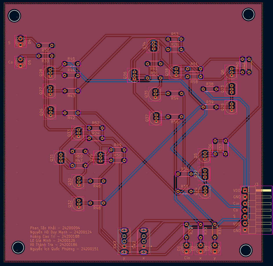
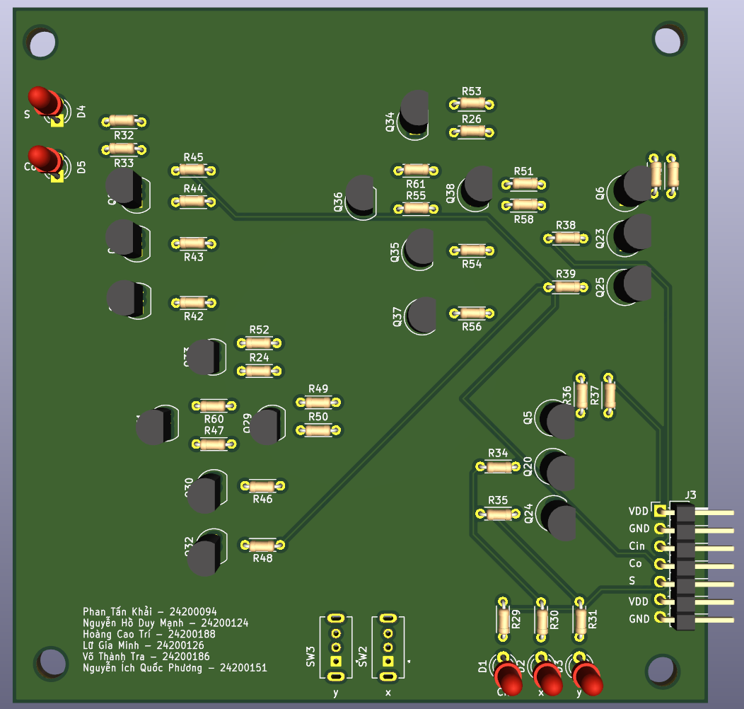


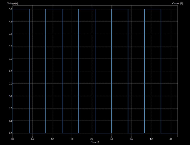
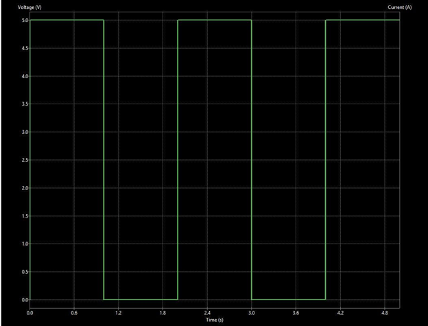
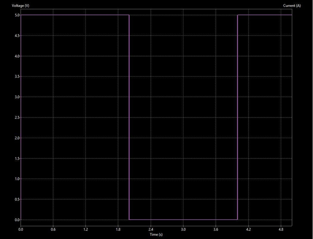
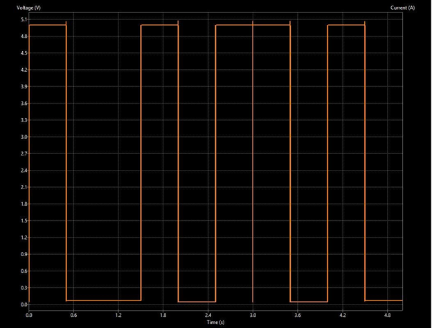
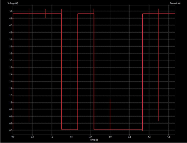
8bit-full-adder/
├── README.md
├── images/
│   ├── pcb/
│   ├── hardware/
│   ├── waveform/
│   └── schematic/
├── kicad_project/
├── docs/⚠️ Important: To correctly view the schematic and PCB, you must open the KiCad project file.
kicad_project/*.kicad_pro⚠️ Do NOT open
.kicad_schor.kicad_pcbdirectly, as some links may not load correctly.
Detailed explanation is available in:
docs/project_overview.mdThis project is intended for educational purposes and demonstrates fundamental concepts in digital logic design and hardware implementation.
| Qty | Value | Footprint | References |
|---|---|---|---|
| 24 | 220k | Resistor_THT:R_Axial_DIN0204_L3.6mm_D1.6mm_P5.08mm_Horizontal | R24, R26, R34, R35, R36, R38, R39, R40, R42, R43, R44, R45, R46, R47, R48, R49 +8 |
| 19 | 2N3904 | Package_TO_SOT_THT:TO-92_Inline | Q20, Q23, Q24, Q25, Q26, Q27, Q28, Q29, Q30, Q31, Q32, Q33, Q34, Q35, Q36, Q37 +3 |
| 5 | 220 | Resistor_THT:R_Axial_DIN0204_L3.6mm_D1.6mm_P5.08mm_Horizontal | R29, R30, R31, R32, R33 |
| 5 | LED | LED_THT:LED_D3.0mm | D1, D2, D3, D4, D5 |
| 4 | 47k | Resistor_THT:R_Axial_DIN0204_L3.6mm_D1.6mm_P5.08mm_Horizontal | R37, R41, R52, R53 |
| 2 | SW_Nidec_CAS-120A1 | Led:SW_SS12D07VG4 | SW2, SW3 |
| 1 | Conn_01x07 | Connector_PinHeader_2.54mm:PinHeader_1x07_P2.54mm_Horizontal | J3 |
It measures 100 × 100 mm and has 2 copper layers, 1.6 mm thick.
60 parts. The full list of its parts is on this page, with links to each part's symbol and footprint where PCBKit's library has them.
From the ctrihoang2006/8bit-full-adder repository on GitHub, at the commit this page was made from: the board is kicad_project/FA 8 bit.kicad_pcb and its schematic kicad_project/AndGate1.kicad_sch. PCBKit opens the board in the browser, with nothing to install.
Its repository states no licence, so its author keeps all rights: ask ctrihoang2006 before reusing the design.


sd2psx/pcb
The PCB must be produced in 0.8mm thickness. Production files are provided under the "Releases" tab. These do not include the through-hole OLED module.


BitDogLab/BitDogLab
Open-source educational hardware for embedded systems, programming, electronics, and physical computing.