2 layers79.5 × 79.5 mm
Esp32-energymeter V2
ElektorLabs/esp32-energymeter
The Elektor ESP32 Energy Meter project, featuring schematics, PCB designs, and ESPHome integration for advanced energy monitoring
116 parts48MIT

 cscott/watchy-co2-pcb13
Simple PCB to mount the Sensirion SCD40 CO2 sensor next to Watchy
Watchy scd40 is an open-source printed circuit board by cscott, from the cscott/watchy-co2-pcb repository on GitHub. It is a 2-layer board of 10.3 × 17 mm with 12 parts on 9 nets, routed with 98 tracks and 14 vias.
It is built around the SCD40-D-R2 and NJM2882F33-TE1. Its parts include 3 capacitors and 2 ICs. It belongs with the sensors and measurement boards of this library.


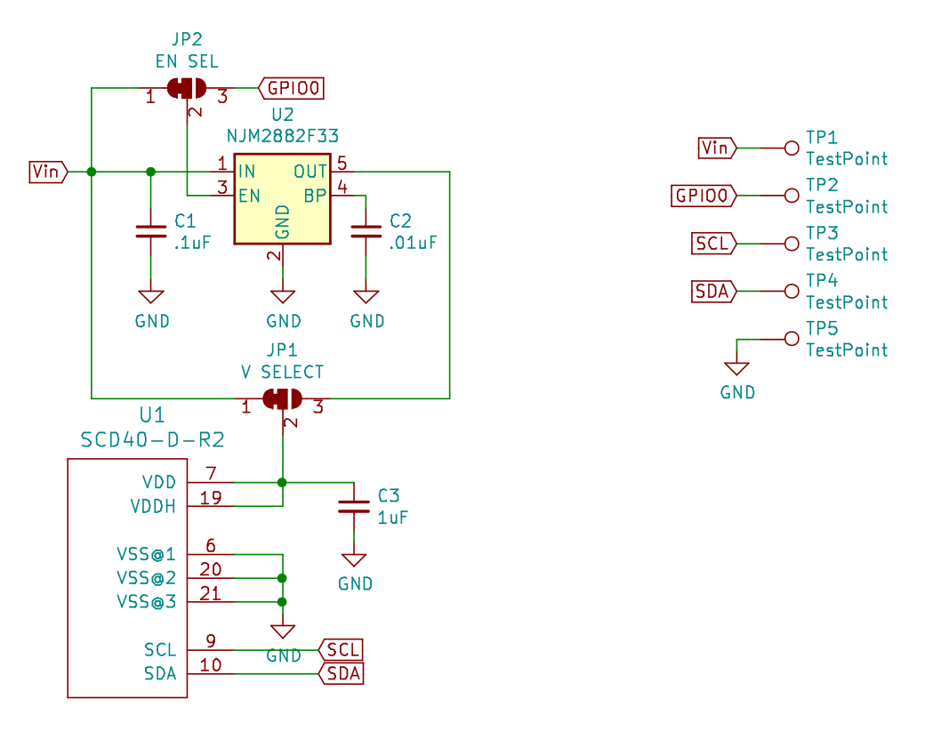
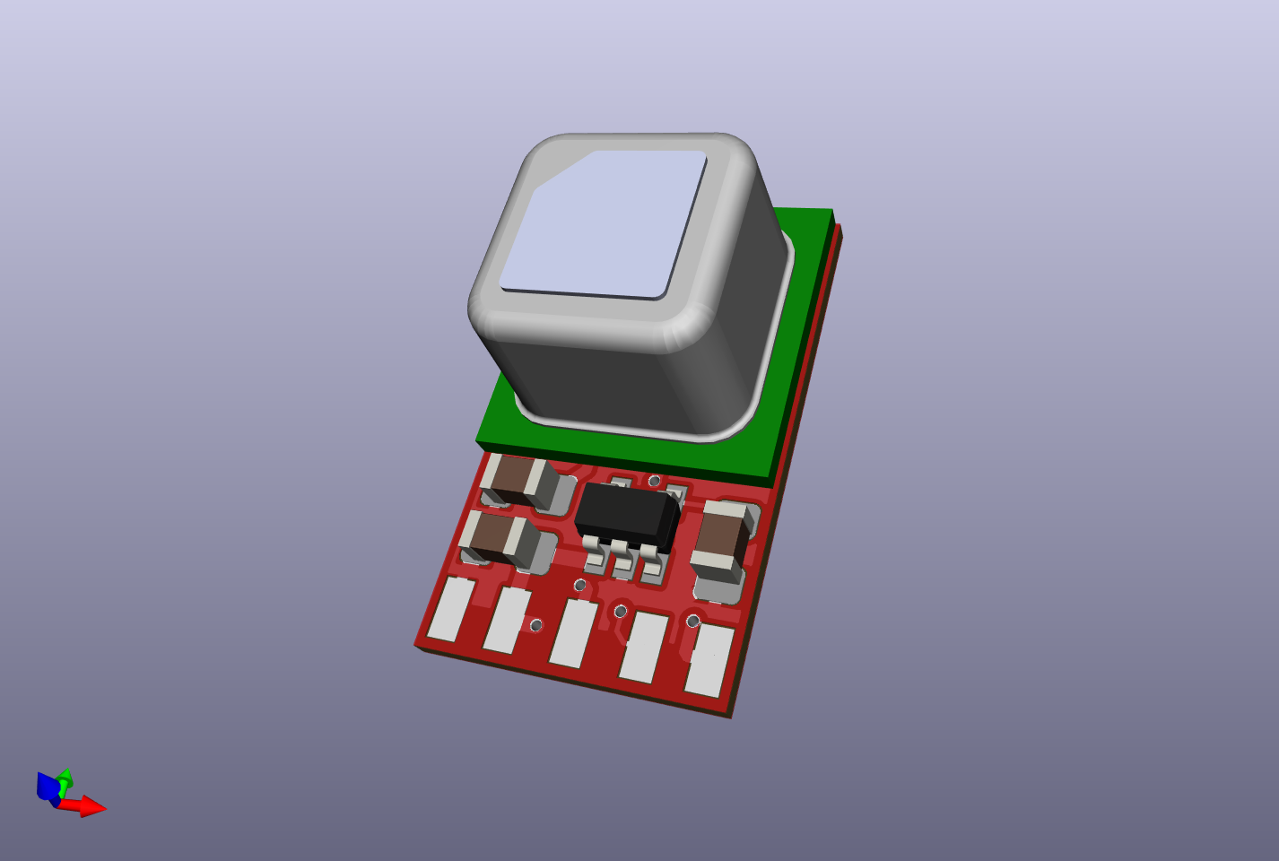
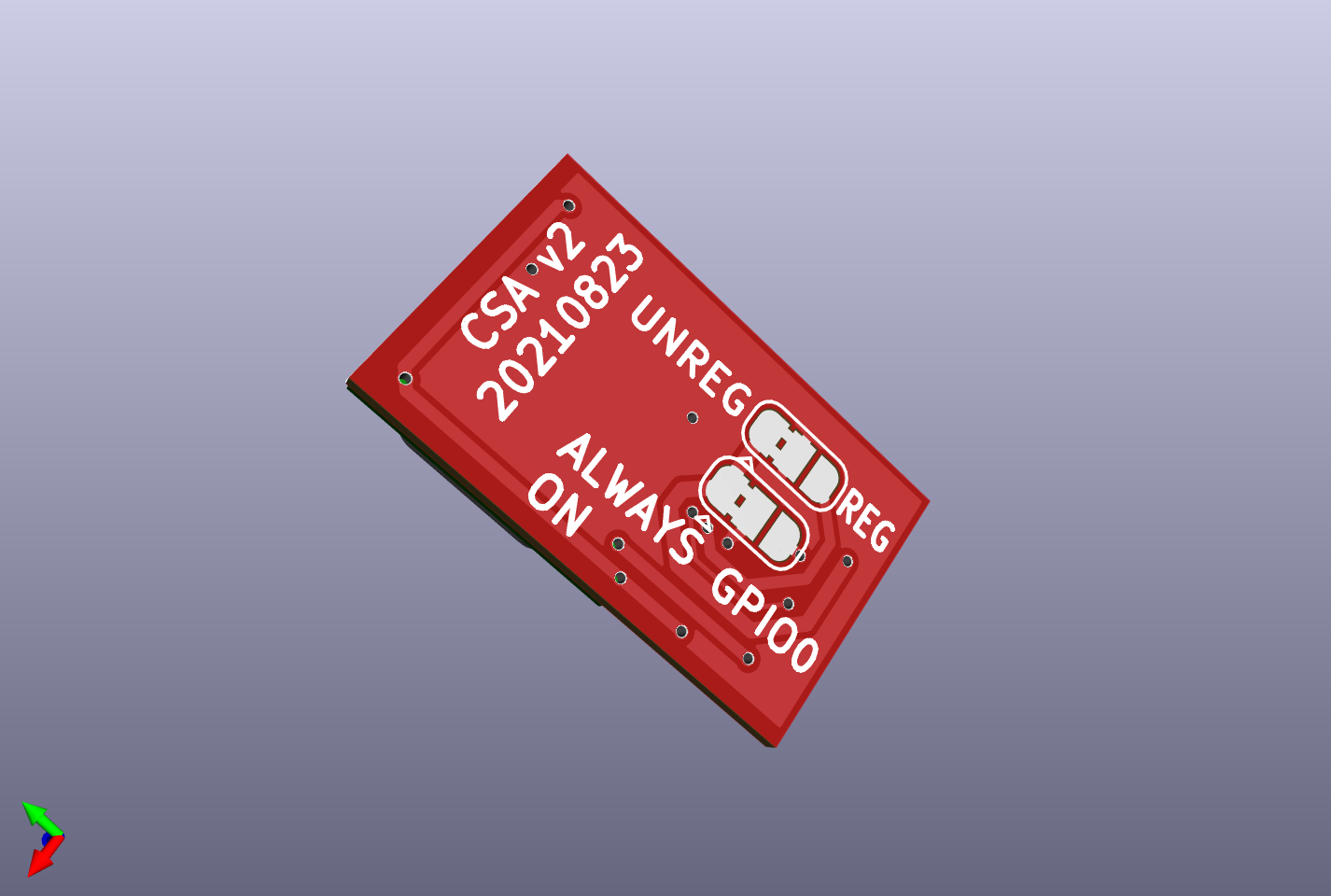
A small 10.3mm x 17mm PCB to mount the Sensirion SCD40/41 CO₂ sensor on. It contains footprints to optionally add a 3.3v LDO regulator and some extra capacitors to better decouple the power supply.
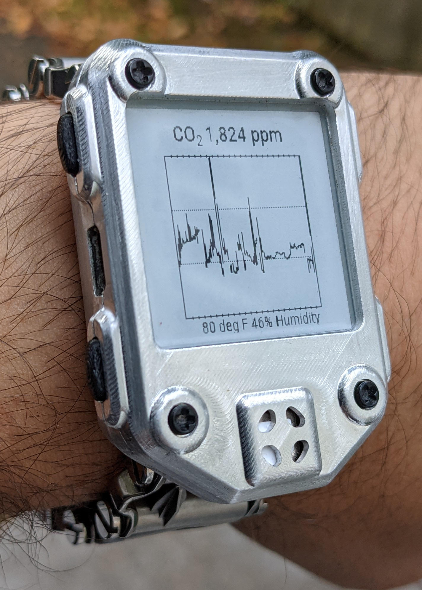
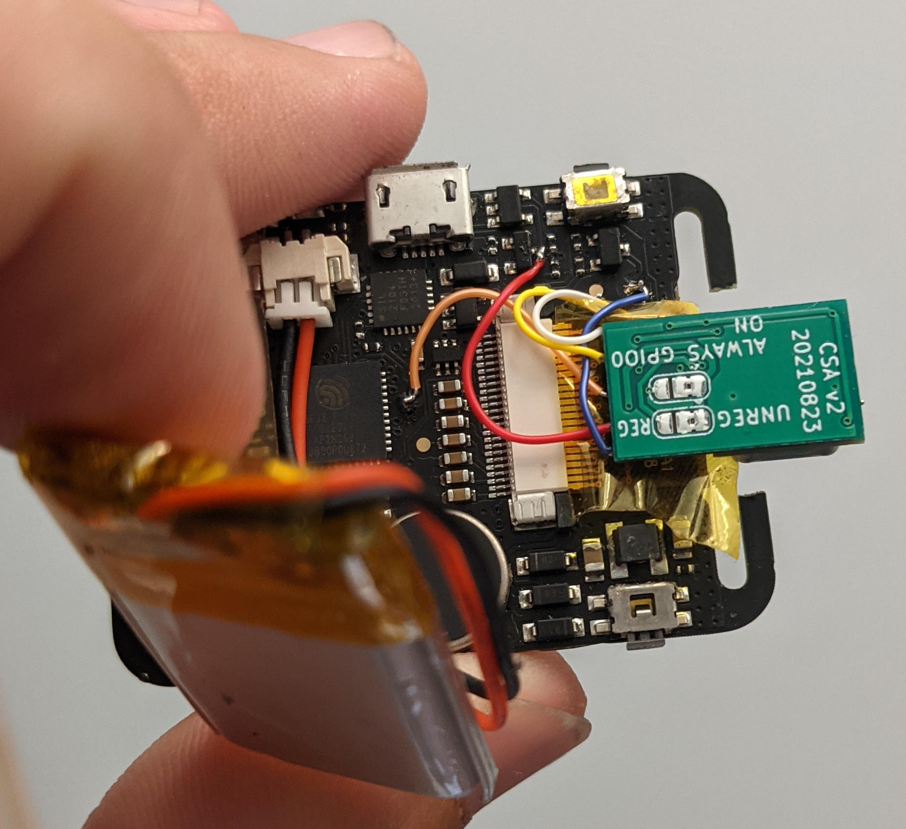
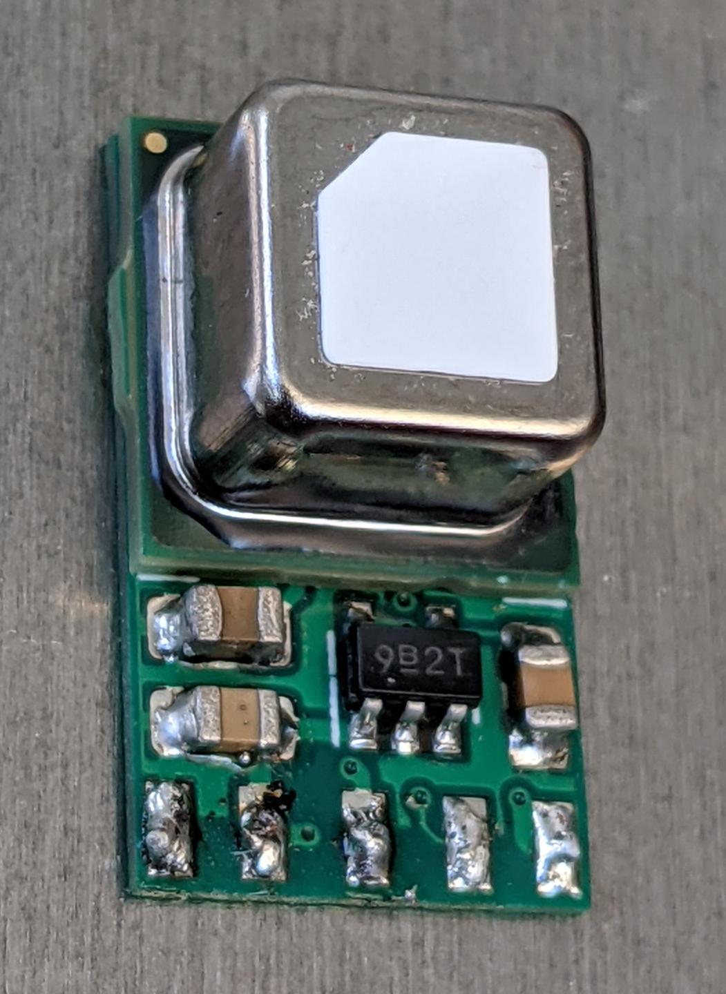
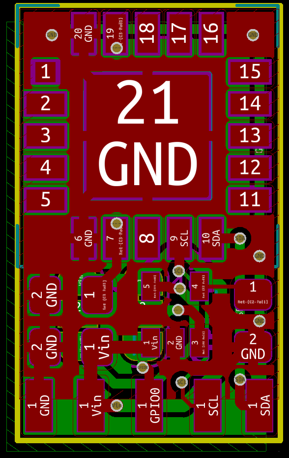
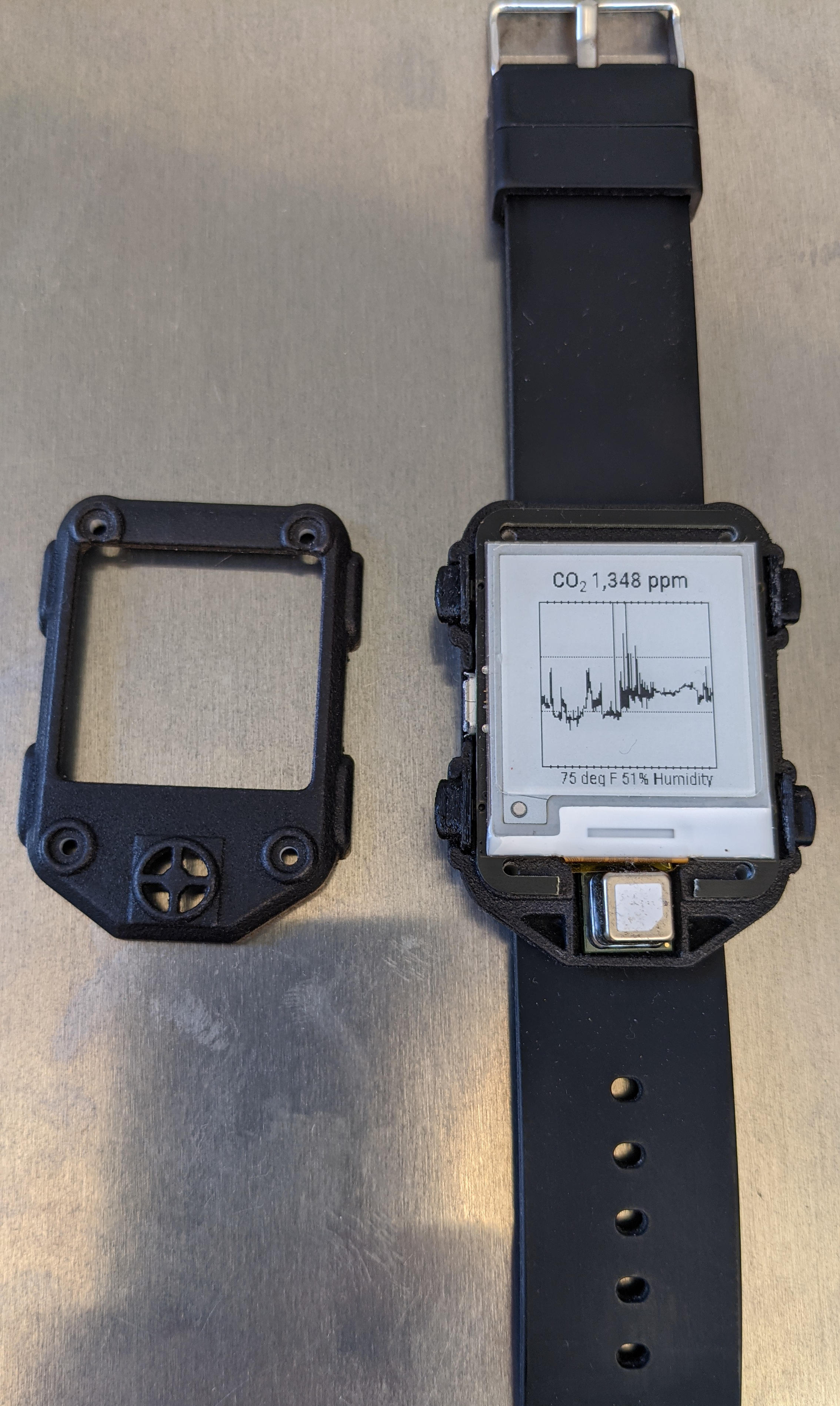
This board is designed to be used with the Watchy Open Source E-Paper Watch. A matching case can be found at cscott/watchy-co2-case, and a watchface using this board can be found at cscott/watchy-c4,
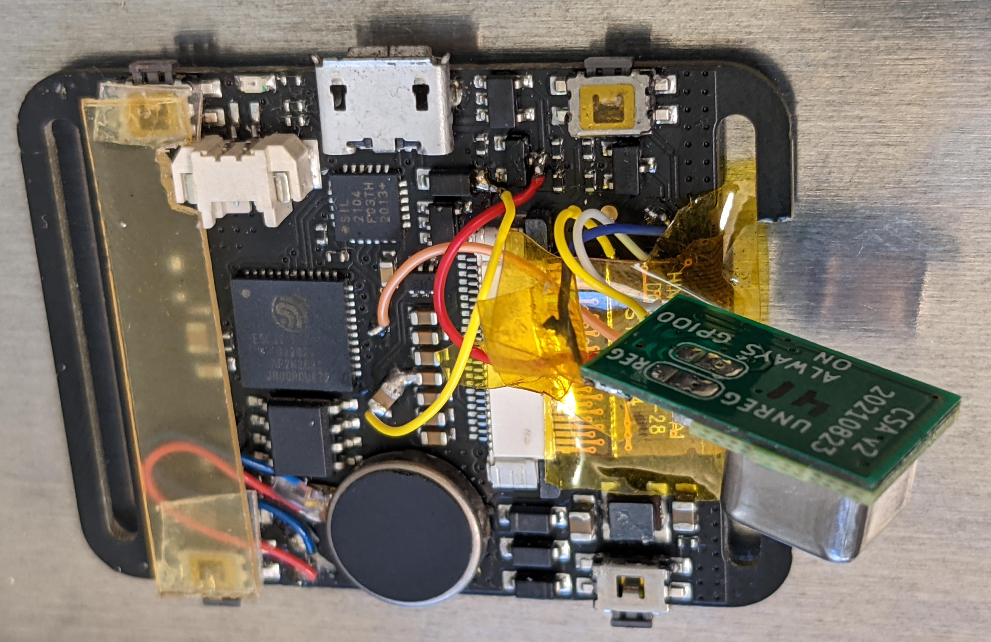
When wiring to Watchy, the SCL/SDA/GND inputs should be wired to the appropriate test points on the Watchy PCB back, as shown below.
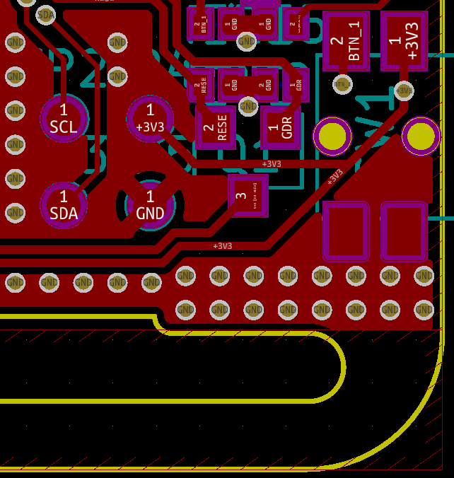
For Vin, there are three options:
The Vin input can be connected to the +3V3 test point above, with JP1 in its default UNREG position. This shares the 3.3V power supply with the main ESP32. It may (or may not) be too noisy for best SCD40 accuracy.
The Vin input can be connected directly to the battery +BATT at one of the positions highlighted in pink below. JP1 would be left in its default UNREG position. This provides the best battery efficiency (the SCD40 can tolerate the higher voltage level), but (depending on the battery internal resistance) again may be too noisy for best SCD40 accuracy. However, this is the configuration I have used in the watches I've assembled.
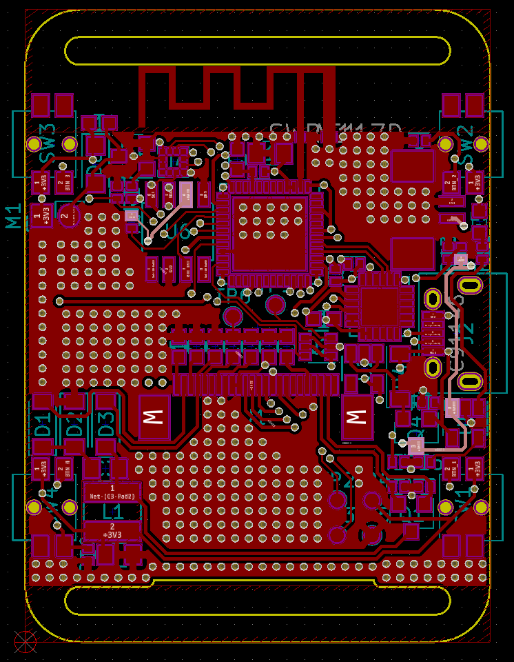
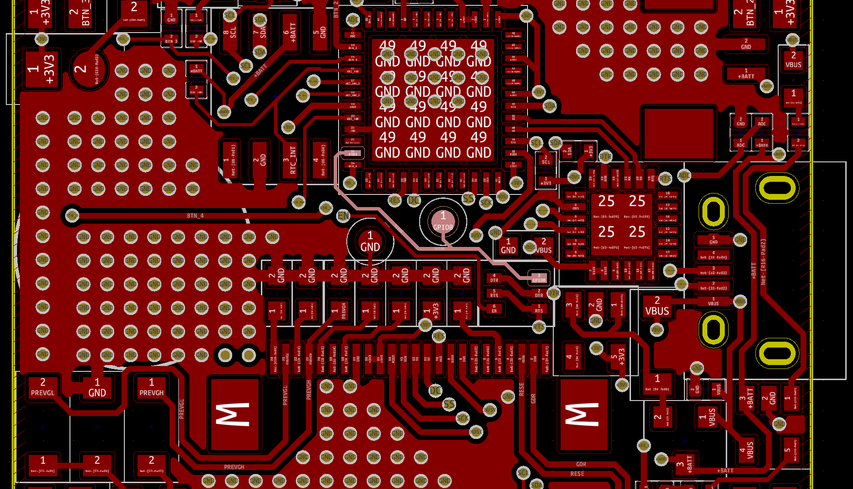
The CP1 and CP3 capacitors will provide useful decoupling in all three configurations, although (depending on noise measurements) they may not be required. All three capacitors and U2 are required in configuration three.
Here's a digikey link for all components.
Note that this board will work with the lower-cost SCD40 sensor, and gets about a day of battery life in this configuration with the stock Watchy battery, reading CO₂ levels every 30 seconds. The slightly more expensive SCD41 sensor has the exact same pinout and footprint, but contains a lower-power mode where it can read the sensor every 5 minutes instead, and power consumption drops from 3.2mA to 0.5mA. (In October 2021 the SCD42 was added to the product lineup which is also footprint-compatible, but this part drops the low power modes and requires 15mA which would make it incompatible with wearable use.)
This board was designed using KiCad 5.
(See also this doc from TI on decoupling techniques using a ferrite bead if further noise reduction is necessary. The Sensirion datasheet for the SCD40 suggests less than 30mV of power supply noise.)
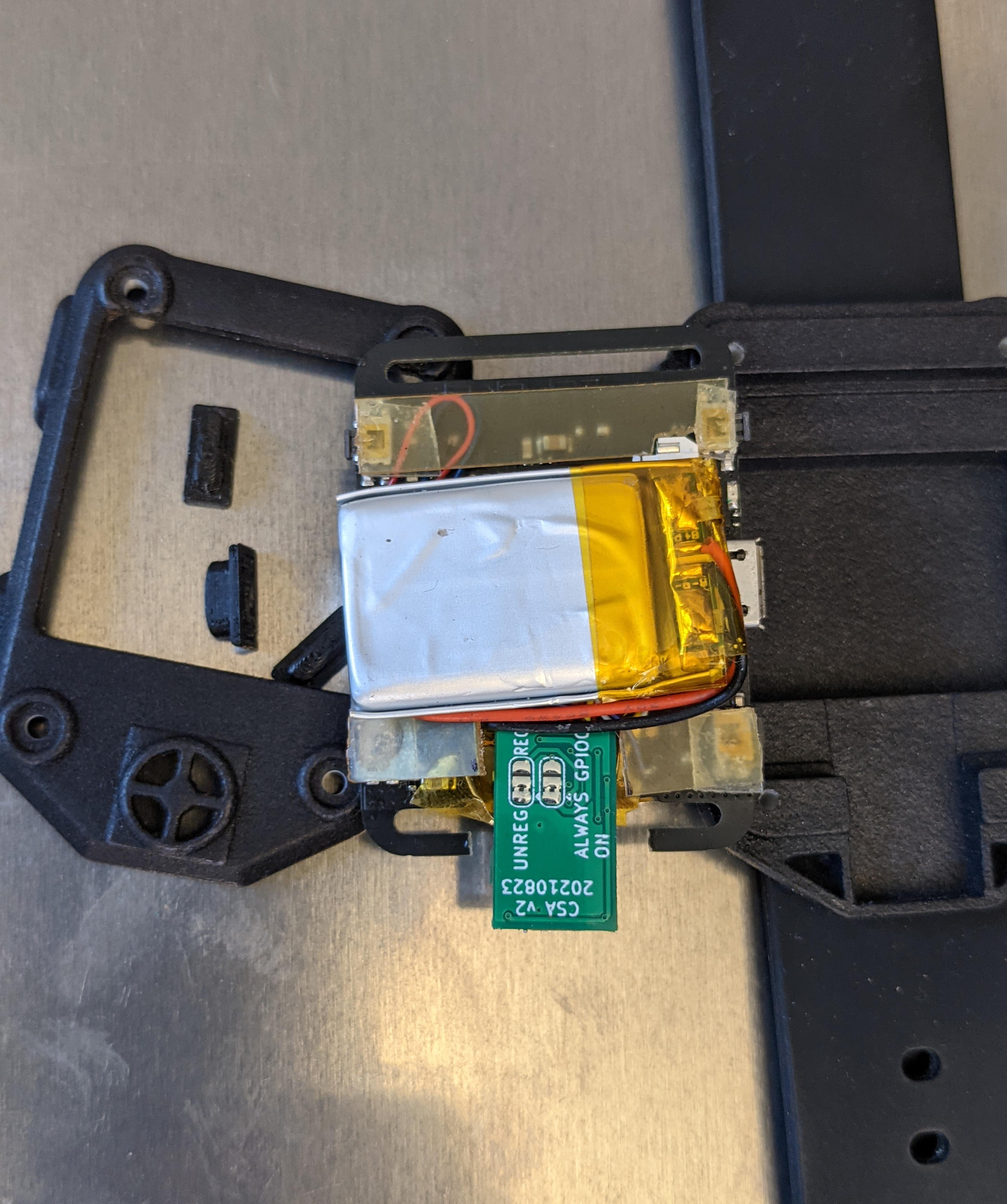
Note that I've connected GPIO in these photos, even though I'm not using
regulator (I'm using power option 2). I also added an extra capacitor,
whose high side is supposed to be connected to pins 5 and 6 of the CP2104
to fix the dreaded "USB death" problem of the first release of the Watchy,
but instead (due to a confusion I had about the PWR_FLAG symbol on the
Watchy schematic, it's connected across the input to U2, the watchy voltage
regulator -- which could also use a capacitor to stabilize the regulator,
but wasn't what I was intending to do...
I also had issues with the watchy button switches popping open because they are not supported on the bottom side; the orangish bits of plastic in these photos are my impromptu shims to allow the bottom side of the switches to be supported by the bottom case half.
| Qty | Value | Footprint | References |
|---|---|---|---|
| 5 | TestPoint | scd40:TestPoint_Pad_2.0x2.0mm-nosilk | TP1, TP2, TP3, TP4, TP5 |
| 1 | .01uF | Capacitor_SMD:C_0805_2012Metric_Pad1.15x1.40mm_HandSolder | C2 |
| 1 | .1uF | Capacitor_SMD:C_0805_2012Metric_Pad1.15x1.40mm_HandSolder | C1 |
| 1 | 1uF | Capacitor_SMD:C_0805_2012Metric_Pad1.15x1.40mm_HandSolder | C3 |
| 1 | EN SEL | Jumper:SolderJumper-3_P1.3mm_Bridged2Bar12_RoundedPad1.0x1.5mm | JP2 |
| 1 | NJM2882F33 | Package_TO_SOT_SMD:SOT-23-5 | U2 |
| 1 | SCD40-D-R2 | scd40:SCD40-D-R2 | U1 |
| 1 | V SELECT | Jumper:SolderJumper-3_P1.3mm_Bridged2Bar12_RoundedPad1.0x1.5mm | JP1 |
ElektorLabs/esp32-energymeter
The Elektor ESP32 Energy Meter project, featuring schematics, PCB designs, and ESPHome integration for advanced energy monitoring


emertcakir/OpenAirScope
Open-source air quality and environmental monitoring node with STM32H743 + ESP32-C3, LoRaWAN, RS485, USB-C, Li-ion charging, and multi-sensor support.


romkey/pdxhackerspace-portable-co2-monitor
Open source hardware and software portable CO2/air quality monitor

Daniel-Abdi/Matter-CO2-AirQuality-Sensor
Create an ESP32-C6 based air quality sensor for Matter. Grab CO2 concentration in real time and update in any Matter compatible app.

nobodyguy/zigbee_air_quality_monitor_hardware
Opensource HA compatible air quality monitor with CO2, temperature and humidity measurements
It measures 10.3 × 17 mm and has 2 copper layers, 0.6 mm thick.
12 parts, built around the SCD40-D-R2 and NJM2882F33-TE1. The full list of its parts is on this page, with links to each part's symbol and footprint where PCBKit's library has them.
From the cscott/watchy-co2-pcb repository on GitHub, at the commit this page was made from: the board is watchy-scd40.kicad_pcb. PCBKit opens the board in the browser, with nothing to install.
Its repository states no licence, so its author keeps all rights: ask cscott before reusing the design.