2 layers42.6 × 59 mm
SolderingTurkey
cscott/maker-day-kit
Schematics and PCB layout for kits for Brookline Public School's 1st Maker Day
11 parts1

 cscott/maker-day-kit1
Schematics and PCB layout for kits for Brookline Public School's 1st Maker Day
StaringTurkey is an open-source printed circuit board by cscott, from the cscott/maker-day-kit repository on GitHub. It is a 2-layer board of 32.2 × 73.8 mm with 7 parts on 8 nets, routed with 53 tracks and 11 vias.
Its parts include 2 diodes and 2 connectors.

Brookline Public Schools are having their first Maker Day on May 11, 2019.
I volunteered to run a "learn to solder" station, and decided to design some simple PCBs. There was already a "make a badge with a blinking LED" station, so I needed to be a little more ambitious... but I wanted to bring the project to cost ~$2/board so we could afford to make 200 of them for the kids.
The idea we came up with was to use the really-cheap Digispark boards (@$1 each from aliexpress) as the basis -- that provides power (via USB and on-board regulator) and basic connectivity, and suggests further take-home activities for the kids and their parents after the event, based on the beloved-by-education Arduino environment. The fantastic turkey art was contributed by Caroline Barnes of brooklineturkeys.com / @BklineTurkeys.
A 9V battery and snap can be soldered into the Vin/GND pads on the digispark.
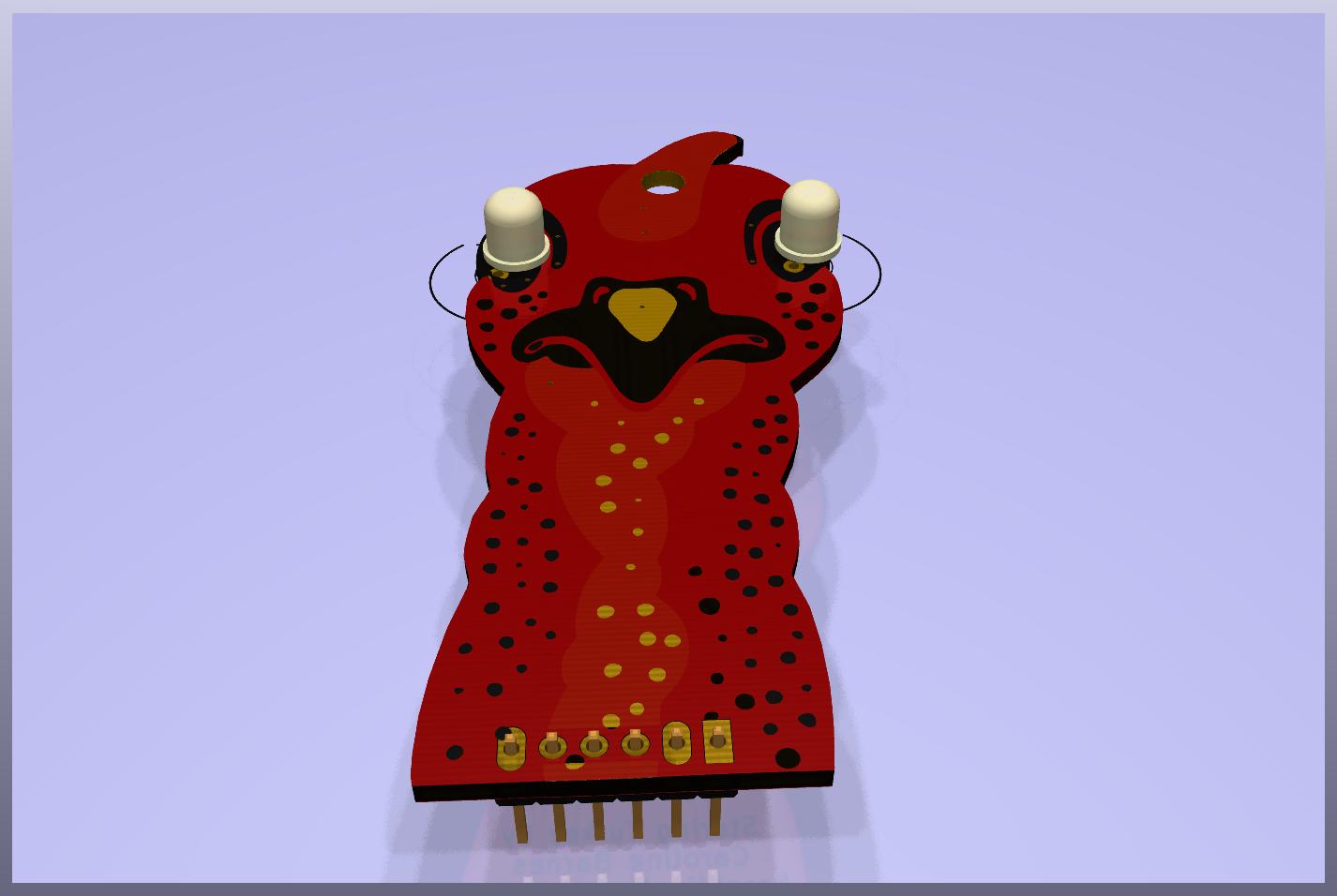
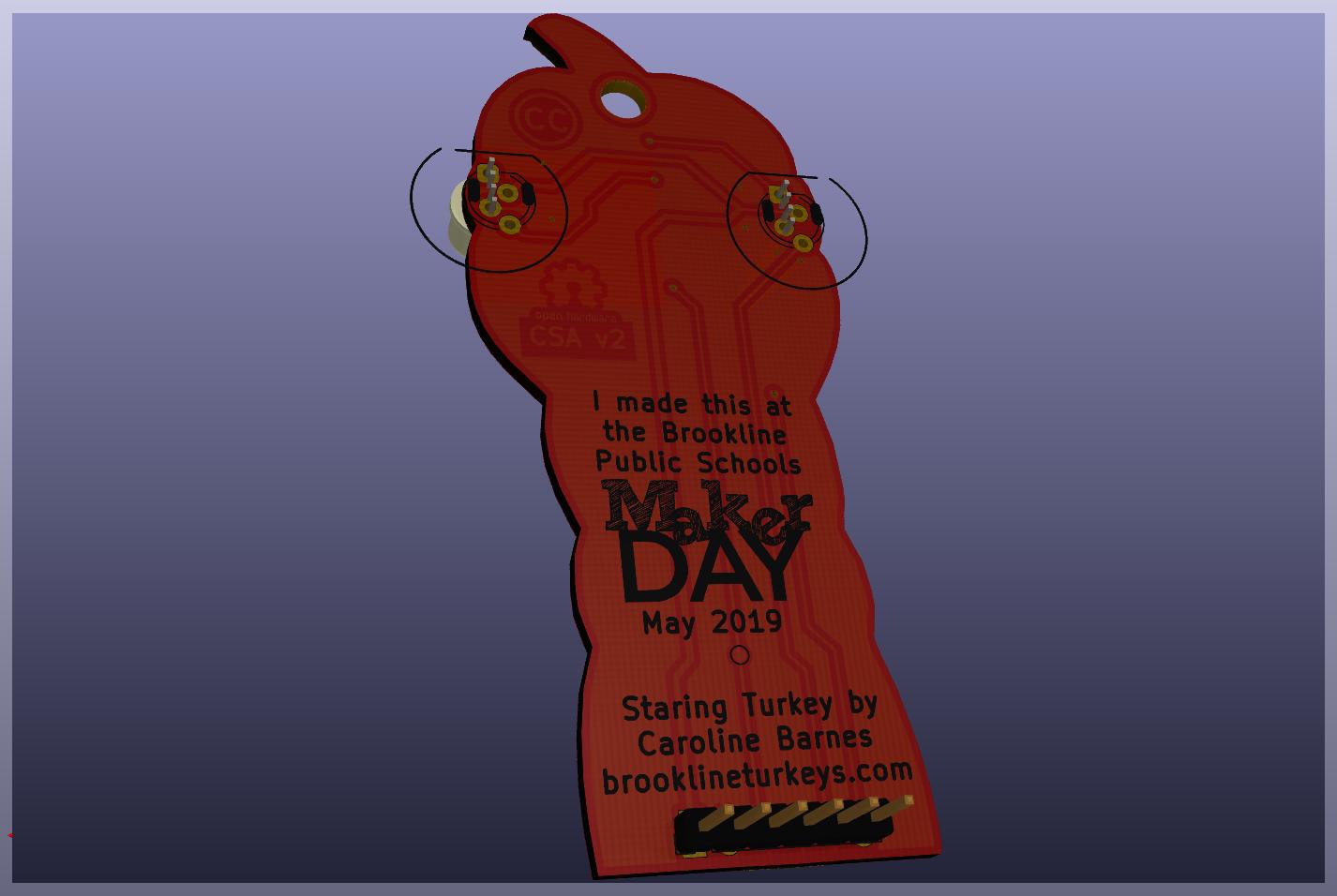
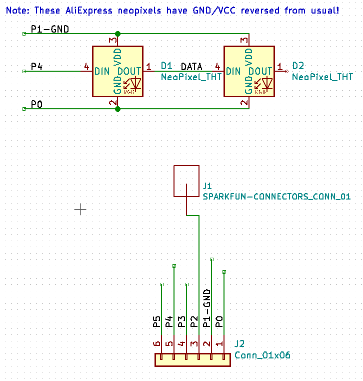
For output: two NeoPixel LEDs, in beginning-solderer-friendly through-hole packages. I've got two basic designs here, and I haven't quite decided which to use in the event. In the "staring turkey", the circuit is just the two neopixels. Conveniently, we don't need current-limiting resistors, and we "cheat" and save the trouble of soldering a separate header for power by using two GPIO pin for +5V and GND. A separate GPIO is connected to the turkey's beak, which should (fingers crossed) provide a simple touch sensitive input. We can imagine fun easter eggs, like allowing you to tap morse code into the beak and having the turkeys eyes flash back a morse code message (see my Ben Bitdiddle puzzle for an example of this UX).
The second board is a bit more ambitious: in addition to two neopixels, this time used to backlight the body of the turkey, we have two "conventional" LEDs for the eye and tip of the soldering iron (and the required series resistors for these). This time the wing of the turkey is the touch sensitive area. I'll have a pile of conventional LEDs in different colors so that kids can choose which colors to use (and a few flashing RGB two-terminal devices). This is a more incremental learning experience for the kids: once they've soldered the bare minumum (the digispark header on the board) they've got a choice of four things to do next: battery snap (let's them run w/o a USB tether), the eye LED + resistor, the soldering iron LED + resistor, or one or two neopixels. They can stop at any point and walk away with something that works. We can distribute handouts with links to the software for the project, the design files, and full assembly instructions (including where to buy a cheap soldering iron on amazon), so they can continue to finish the project at home -- spreading maker culture, which is the real point of the day!
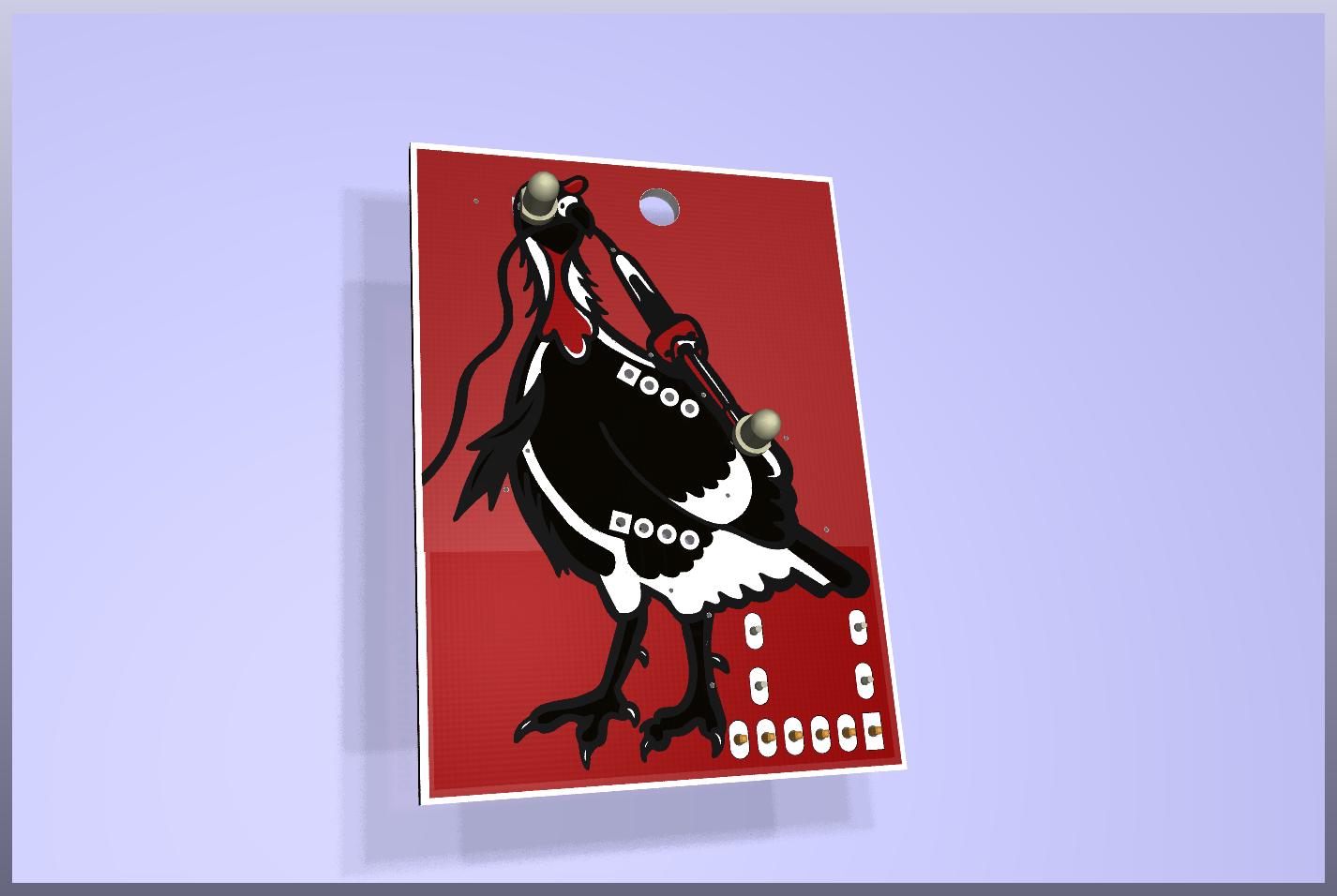
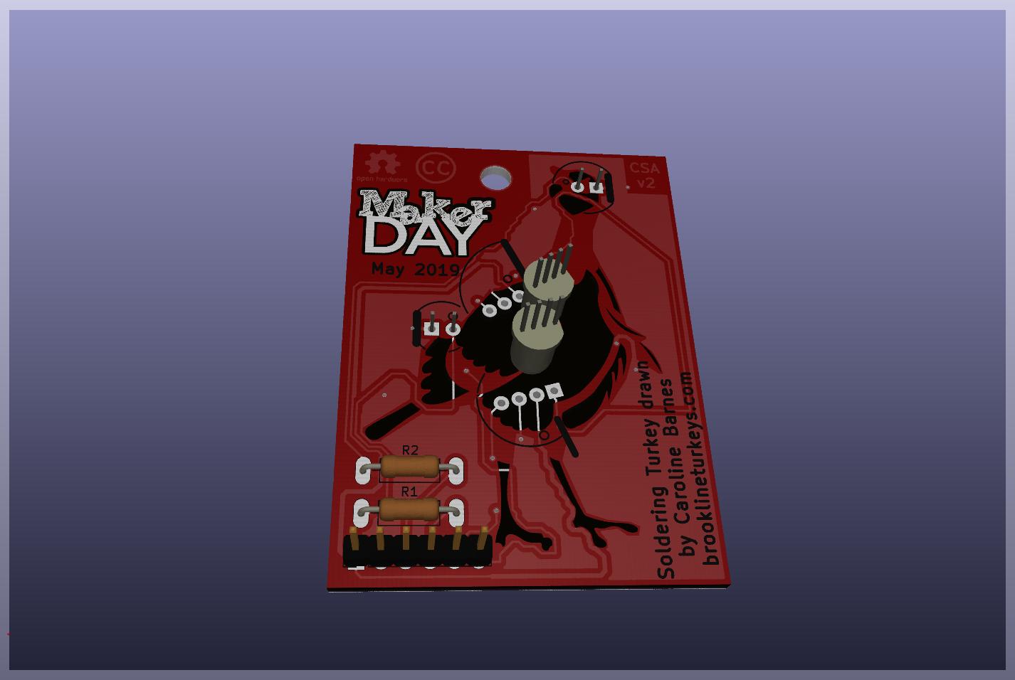
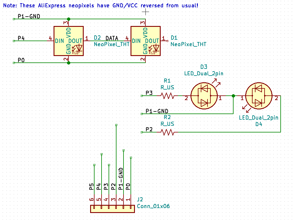
I just ordered the PCBs from pcbway in quantity 200. Fingers crossed they all work correctly when I get them back!
I still haven't decided which design to use on Maker Day, but if I screwed up one of the boards my decision will be easy. ;)
-- C. Scott Ananian, Apr 8, 2019
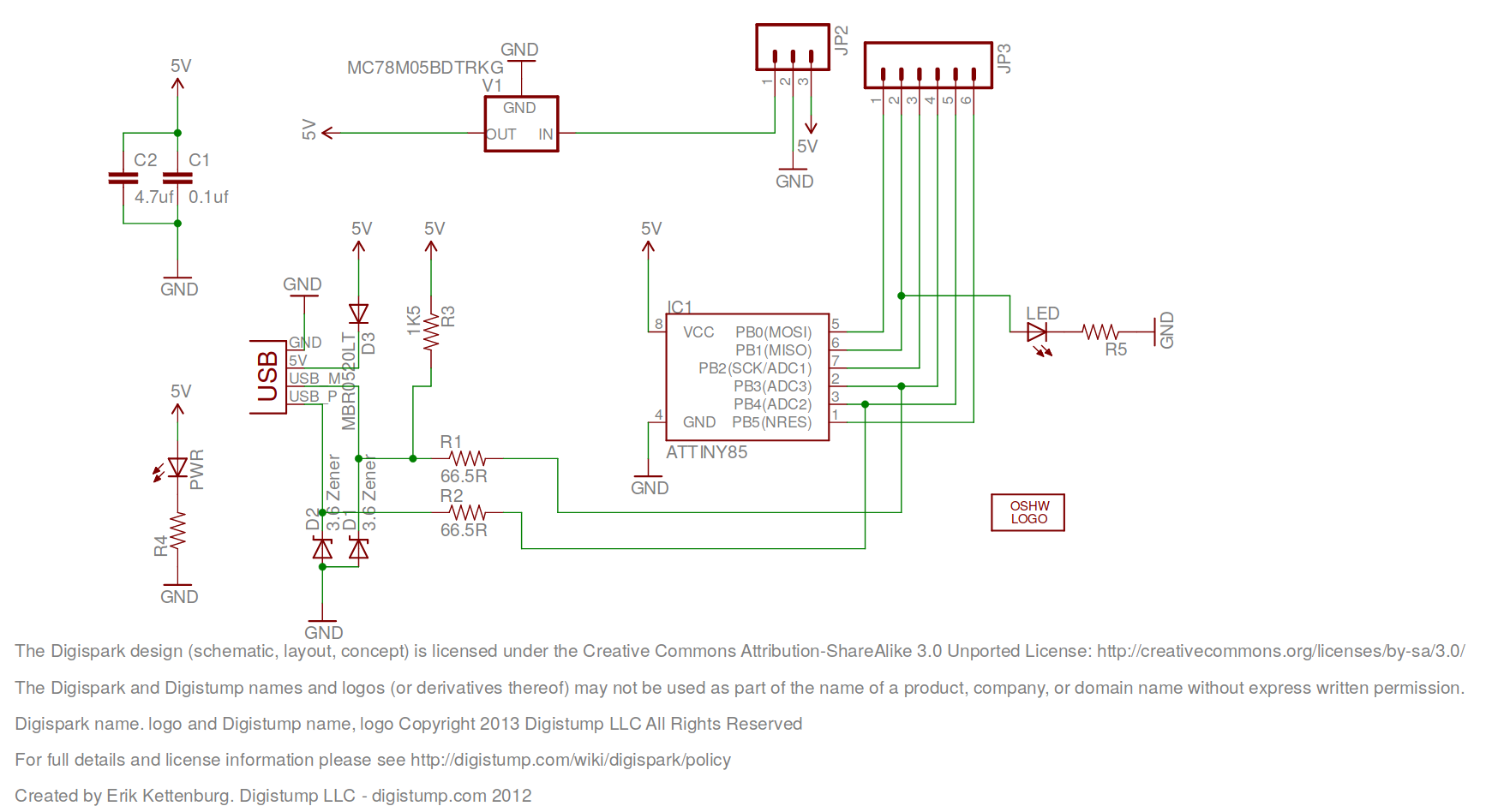
Here's the Digispark Schematic and here's the DigiSpark wiki with lots of software and getting-started information.
The SAO tutorial video and PCB color guide by TwinkleTwinkie have been great helps!
Brian Benchoff's KiCad tutorial series taught me how to use KiCad, and his article on BOM cost optimization had a few useful pointers for this project as well.
Uri Shaked's article on PCB art helped me explain this whole #badgelife thing to others.
Shea Silverman's PCBArt article walked me through using the Inkscape svg2shenzhen extension.
| Qty | Value | Footprint | References |
|---|---|---|---|
| 2 | NeoPixel_THT | svg:LED_D5.0mm-4_RGB_Staggered_Pins_BackSilk | D1, D2 |
| 1 | Conn_01x06 | Connector_PinHeader_2.54mm:PinHeader_1x06_P2.54mm_Vertical | J2 |
| 1 | SPARKFUN-AESTHETICS_OSHW-LOGOS | Symbol:OSHW-Logo2_7.3x6mm_Copper | LOGO1 |
| 1 | SPARKFUN-CONNECTORS_CONN_01 | TestPoint:TestPoint_Pad_D1.0mm | J1 |
| 1 | Val** | svg:PCB-staring-turkey | Ref** |
| 1 | Val** | svg:logo-silk | Ref** |
cscott/maker-day-kit
Schematics and PCB layout for kits for Brookline Public School's 1st Maker Day

byrantech/laptop
anyon_e, a highly integrated, high end, open source laptop. Attempt the impossible.


AxxAxx/AxxSolder
STM32 Based soldering station for JBC cartridges, 9-24 VDC and USB-PD power


jamro/tiny-engineer
A small desktop robot that brings an AI coding assistant to life, physically acting out when it reads files, thinks, writes code, and finishes work.

hoglet67/RGBtoHDMI
Bare-metal Raspberry Pi project that provides pixel-perfect sampling of Retro Computer RGB/YUV video and conversion to HDMI

It measures 32.2 × 73.8 mm and has 2 copper layers, 1.6 mm thick.
7 parts. The full list of its parts is on this page, with links to each part's symbol and footprint where PCBKit's library has them.
From the cscott/maker-day-kit repository on GitHub, at the commit this page was made from: the board is StaringTurkey/StaringTurkey.kicad_pcb. PCBKit opens the board in the browser, with nothing to install.
Its repository states no licence, so its author keeps all rights: ask cscott before reusing the design.