2 layers118.7 × 86.4 mm
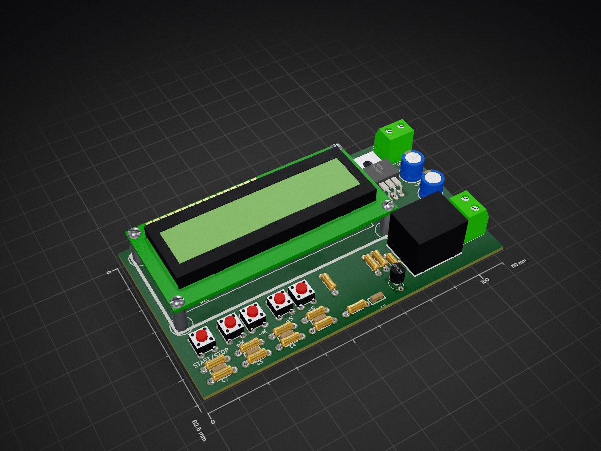
 crisap94/Timer-PCB
Timer board Using Attiny85 as brain.
Timer is an open-source printed circuit board by crisap94, from the crisap94/Timer-PCB repository on GitHub. It is a 2-layer board of 110 × 62.5 mm with 36 parts on 35 nets, routed with 295 tracks and 0 vias.
It is built around the PCF8574T, LM7805CT and BC547. Its parts include 13 resistors, 7 capacitors, 5 switches, 3 ICs and 2 transistors. It belongs with the AVR (ATmega, ATtiny) boards of this library.


| Qty | Value | Footprint | References |
|---|---|---|---|
| 7 | 10k | w_pth_resistors:RC03 | R1, R3, R8, R9, R10, R11, R12 |
| 5 | 0.1uF | w_capacitors:cnp_3mm_disc | C3, C4, C5, C6, C7 |
| 4 | 4.6k | w_pth_resistors:RC03 | R4, R5, R6, R7 |
| 2 | BC547 | TO_SOT_Packages_THT:TO-92_Inline_Wide | Q1, Q2 |
| 1 | +M | w_switch:PCB_PUSH | SW2 |
| 1 | +S | w_switch:PCB_PUSH | SW4 |
| 1 | -M | w_switch:PCB_PUSH | SW3 |
| 1 | -S | w_switch:PCB_PUSH | SW5 |
| 1 | 1000uF | w_capacitors:CP_8x11.5mm | C1 |
| 1 | 10k | w_pth_resistors:trimmer_piher_pt6xv | RV1 |
| 1 | 1k | w_pth_resistors:RC03 | R2 |
| 1 | 470uF | w_capacitors:CP_8x11.5mm | C2 |
| 1 | 560 | w_pth_resistors:RC03 | R13 |
| 1 | ATTINY85-P | w_pth_circuits:dil_8-300_socket | IC1 |
| 1 | D | w_pth_diodes:diode_do35 | D1 |
| 1 | LCD16X2 | w_indicators:lcd_16x2 | DS1 |
| 1 | LEDS | w_conn_screw:mors_2p | P1 |
| 1 | LM7805CT | TO_SOT_Packages_THT:TO-220_Neutral123_Horizontal_LargePads | U2 |
| 1 | PCF8574 | w_pth_circuits:dil_16-300_socket | U1 |
| 1 | PWR | w_conn_screw:mors_2p | P2 |
| 1 | RELAY_HJR-3FF_Z | w_relay:relay_hjr-3ff_z | RLY1 |
| 1 | START/STOP | w_switch:PCB_PUSH | SW1 |
It measures 110 × 62.5 mm and has 2 copper layers, 1.6 mm thick.
36 parts, built around the PCF8574T, LM7805CT and BC547. The full list of its parts is on this page, with links to each part's symbol and footprint where PCBKit's library has them.
From the crisap94/Timer-PCB repository on GitHub, at the commit this page was made from: the board is Timer.kicad_pcb. PCBKit opens the board in the browser, with nothing to install.
Its repository states no licence, so its author keeps all rights: ask crisap94 before reusing the design.

dirkjankrijnders/lnet-iface-hub
Modular hub/frontpanel/microcontroller interface PCB's

sarfata/ebus-adapter
This is a read/write adapter for eBus heating bus. It can be connected to a USB-serial adapter (3.3V or 5V) - or to a Particle Photon.

alan05code/Distributore
Distributore Smart | Progetto Scolastico 2023/2024 | Client (PCB) + Server(RaspBerry) + SitoWeb(HTML/CSS/JavaScript) + Simulazione(Python)


EleonoreMizo/pedalevite
Pédale Vite — DIY multi-FX pedalboard for guitar/bass/etc.

ThomasVDD/SmartSupply
SmartSupply is a digital battery powered lab powersupply. It is Arduino compatible and can be controlled via PC over USB.