4 layers60 × 79 mm
Speaking clock smd
lhm0/talking_clock
A talking clock for visually impaired users. ESP32 controlled, fully offline, long battery life.
89 parts1

 crides/zeub
A pixel clock and IoT hub
Zeub is an open-source printed circuit board by crides, from the crides/zeub repository on GitHub. It is a 2-layer board of 180 × 60 mm with 406 parts on 196 nets, routed with 3,228 tracks and 742 vias.
It is built around the W25Q128JVSIQ, DS3231MZ/V+ and LTC4054ES5-4.2#PBF, with the SRV05-4 and AO3400A among its other parts. Its parts include 324 diodes, 23 resistors, 20 capacitors, 12 ICs and 7 connectors. It belongs with the home automation and IoT and lEDs and displays boards of this library.


zeub is meant to be a pixel clock and a IoT hub. The name comes from a smooshed version of zeit (German for time) and hub.
It currently has:
Version 2 assembled displaying a clock icon and time (the right side is green because uh.. I messed up the PCBA parts assignment): 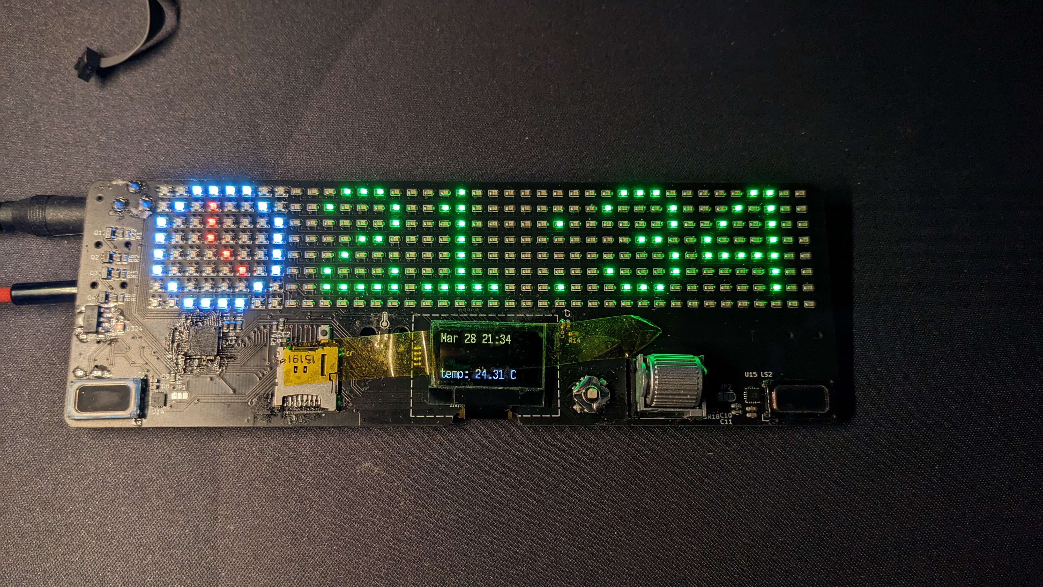
The current firmware fetches the current time (once; supports connection at 2 times for drift correction) from a CTS (Current Time Service) from a BLE connection. This is currently done using my phone through the nRF Connect app. The time is then displayed on both the LED matrix (along with a clock icon), and the OLED along with the date and current temperature. It also sets the brightness of one LED strip using a preconfigured (but can be reconfigured through BLE) schedule. The other LED strip (which is actually my desk light) is controlled by the scroll wheel. It also streams audio from the USB to the speakers, for testing of the audio interface.
The hub part of the project still doesn't really exist yet, as I haven't had time to get to it.
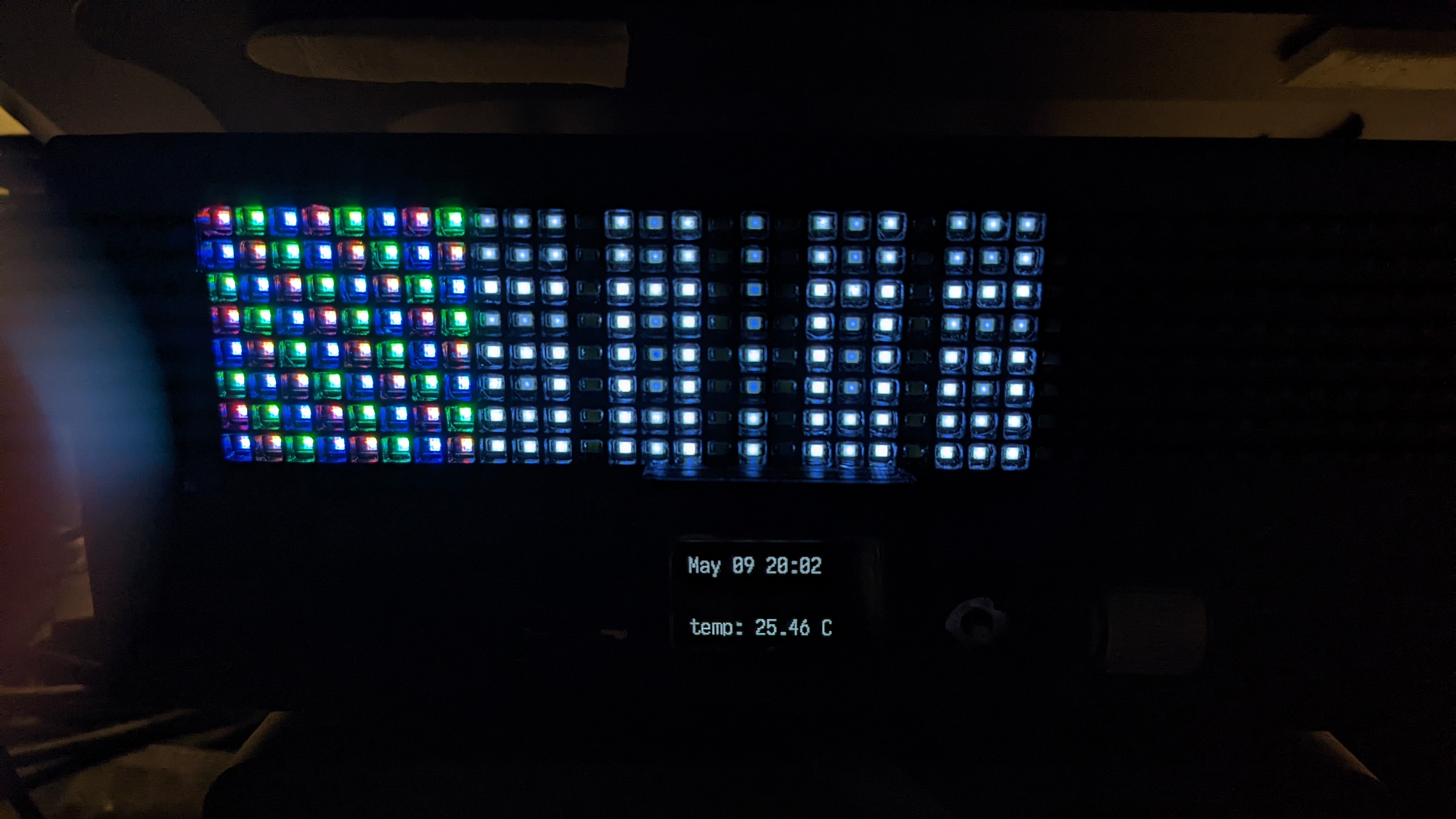
Version 1 has basically the same features, but also included 2 microphones for testing. However the LED matrix did not work properly as I used 2 LED matrix controllers together in the same matrix.
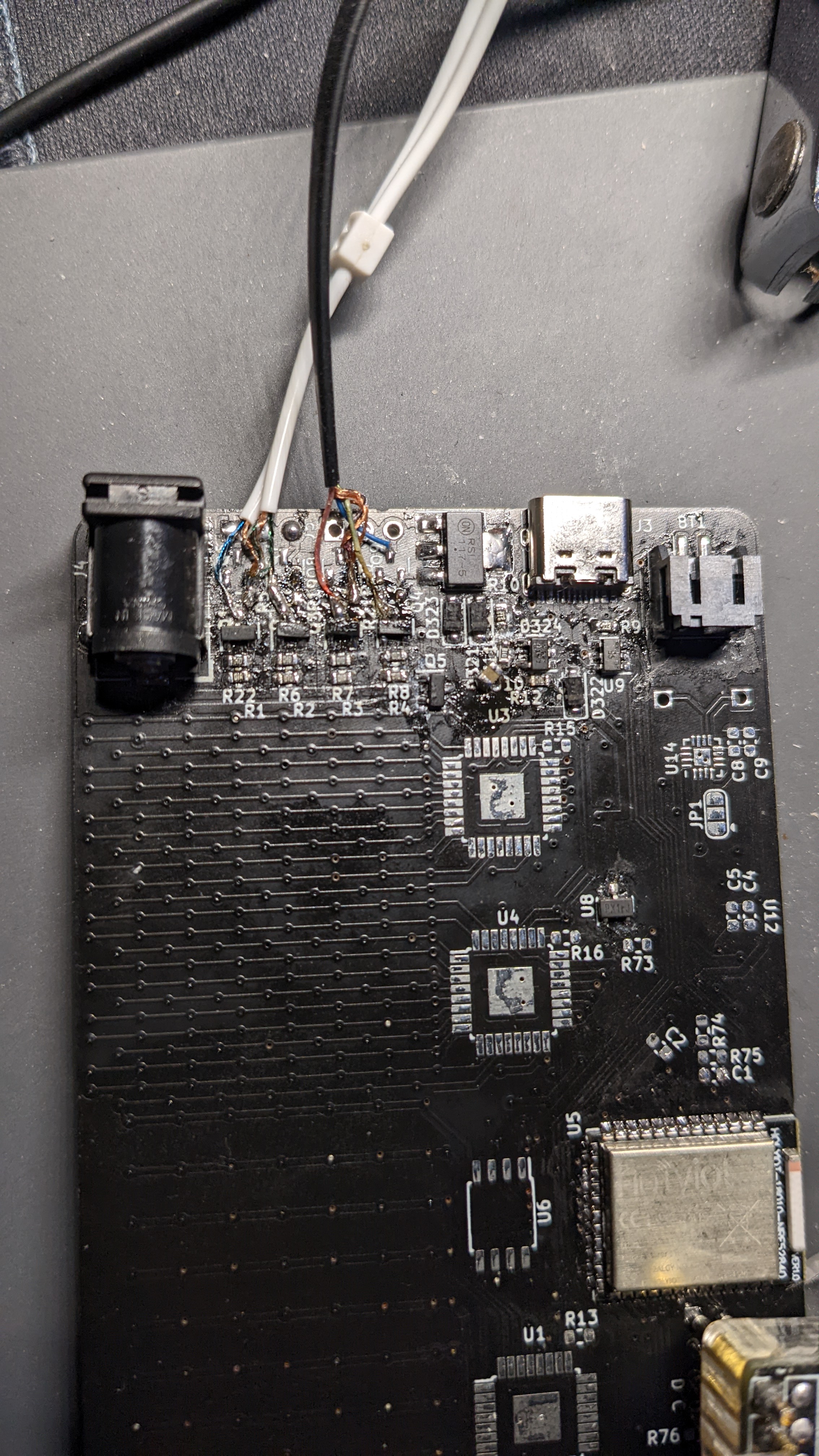
The LED strips were also connected through a TRRS cable but without an actual connector, as I flipped the control polarity of the LED strips (they are common anode instead of common cathode).
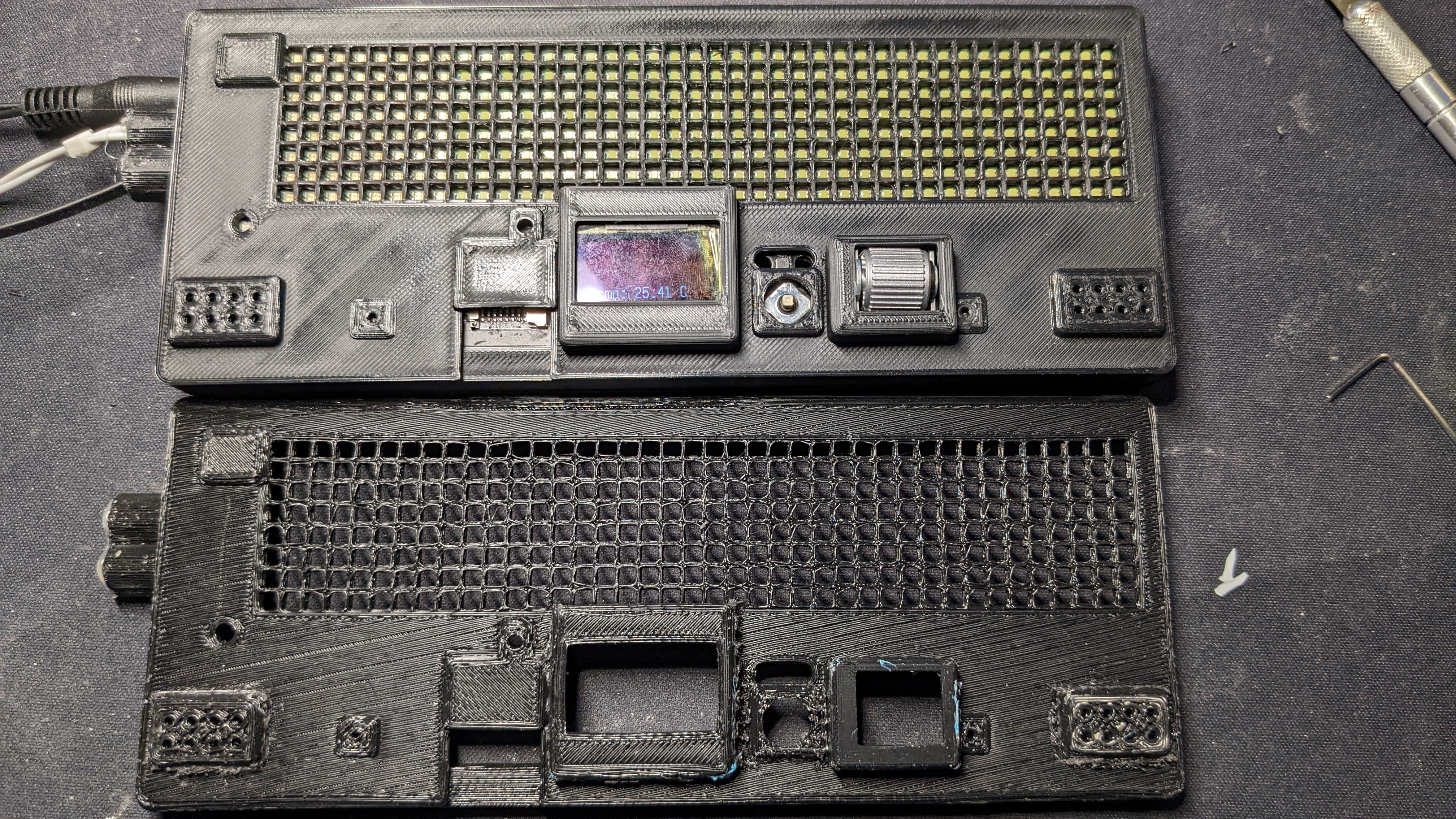
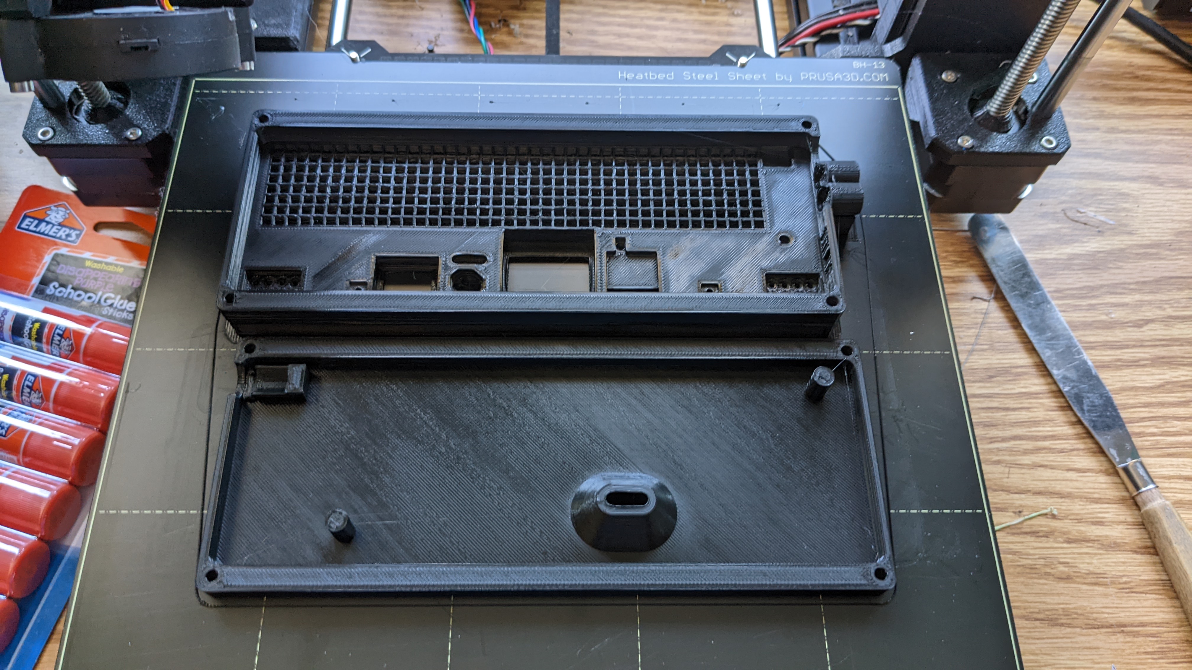
Case iterations for v1 (the cone in the back is for better airflow to the temperature sensor, for more accurate reading of the environment):
| Qty | Value | Footprint | References |
|---|---|---|---|
| 256 | white | Diode_SMD:D_0603_1608Metric | D1, D10, D11, D100, D101, D102, D103, D104, D105, D106, D107, D108, D109, D110, D111, D112 +240 |
| 64 | LED_BGRA | LED_SMD:LED_ASMB-KTF0-0A306 | D257, D258, D259, D260, D261, D262, D263, D264, D265, D266, D267, D268, D269, D270, D271, D272 +48 |
| 10 | 100k | Resistor_SMD:R_0603_1608Metric | R5, R6, R7, R8, R17, R18, R22, R73, R74, R75 |
| 8 | 0.1uF | Capacitor_SMD:C_0603_1608Metric | C3, C5, C6, C8, C10, C13, C14, C20 |
| 8 | 1uF | Capacitor_SMD:C_0603_1608Metric | C2, C4, C7, C12, C15, C17, C18, C19 |
| 5 | AO3400A | Package_TO_SOT_SMD:SOT-23 | Q1, Q2, Q3, Q4, Q5 |
| 4 | 100 | Resistor_SMD:R_0603_1608Metric | R1, R2, R3, R4 |
| 3 | 10k | Resistor_SMD:R_0603_1608Metric | R12, R14, R16 |
| 3 | AudioJack4 | Connector_Audio:Jack_3.5mm_PJ320D_Horizontal | J2, J5, J6 |
| 3 | D_Schottky | Diode_SMD:D_SOD-123 | D321, D322, D323 |
| 2 | 10uF | Capacitor_SMD:C_0603_1608Metric | C9, C11 |
| 2 | 2.2k | Resistor_SMD:R_0603_1608Metric | R76, R77 |
| 2 | 5.1k | Resistor_SMD:R_0603_1608Metric | R9, R10 |
| 2 | IS31FL3741 | ic:QFN-60-1EP_7x7mm_P0.4mm_EP5.4x5.4mm_ThermalVias | U1, U2 |
| 2 | MAX98357A | Package_DFN_QFN:QFN-16-1EP_3x3mm_P0.5mm_EP1.45x1.45mm | U14, U15 |
| 2 | SolderJumper_2_Open | Jumper:SolderJumper-2_P1.3mm_Open_TrianglePad1.0x1.5mm | JP3, JP4 |
| 2 | SolderJumper_3_Open | Jumper:SolderJumper-3_P1.3mm_Open_RoundedPad1.0x1.5mm | JP1, JP2 |
| 2 | Speaker | misc:CMS1609 | LS1, LS2 |
| 1 | 1k | Resistor_SMD:R_0603_1608Metric | R11 |
| 1 | 2.2uF | Capacitor_SMD:C_0603_1608Metric | C16 |
| 1 | 390k | Resistor_SMD:R_0603_1608Metric | R13 |
| 1 | 4.7uF | Capacitor_SMD:C_0603_1608Metric | C1 |
| 1 | Barrel_Jack_Switch | Connector_BarrelJack:BarrelJack_CUI_PJ-102AH_Horizontal | J4 |
| 1 | Battery_Cell | Connector_JST:JST_PH_S2B-PH-SM4-TB_1x02-1MP_P2.00mm_Horizontal | BT1 |
| 1 | DS3231MZ | Package_SO:SOIC-8_3.9x4.9mm_P1.27mm | U3 |
| 1 | LED | Diode_SMD:D_0805_2012Metric | D324 |
| 1 | LTC4054ES5-4.2 | Package_TO_SOT_SMD:TSOT-23-5 | U10 |
| 1 | Micro_SD_Card_Det | misc:molex-503182-1852 | J7 |
| 1 | OLED-128O064D | Display:OLED-128O064D | DS1 |
| 1 | RotaryEncoder_Switch | switch:EVQWGD001 | SW2 |
| 1 | SKRHA | switch:SKRHA-boss | SW1 |
| 1 | SRV05-4 | Package_TO_SOT_SMD:SOT-23-6 | U9 |
| 1 | SW_Push | Button_Switch_SMD:SW_SPST_B3U-1000P | SW3 |
| 1 | TLV1117-50 | Package_TO_SOT_SMD:SOT-223 | U7 |
| 1 | TMP117 | Package_SON:WSON-6-1EP_2x2mm_P0.65mm_EP1x1.6mm | U11 |
| 1 | USB_C_Receptacle_USB2.0 | Connector_USB:USB_C_Receptacle_HRO_TYPE-C-31-M-12 | J3 |
| 1 | W25Q128JVS | Package_SO:SOIC-8_5.23x5.23mm_P1.27mm | U6 |
| 1 | XC6206PxxxMR | Package_TO_SOT_SMD:SOT-23-3 | U8 |
| 1 | holyiot-18010-no-underside | mcu:holyiot-18010-no-underside | U5 |
| 1 | jlink | Connector_PinHeader_1.27mm:PinHeader_2x05_P1.27mm_Vertical_SMD | J1 |
The 402 most common of 406 parts.
It measures 180 × 60 mm and has 2 copper layers, 1.6 mm thick.
406 parts, built around the W25Q128JVSIQ, DS3231MZ/V+, LTC4054ES5-4.2#PBF and SRV05-4. The full list of its parts is on this page, with links to each part's symbol and footprint where PCBKit's library has them.
From the crides/zeub repository on GitHub, at the commit this page was made from: the board is pcb/zeub.kicad_pcb and its schematic pcb/audio.kicad_sch. PCBKit opens the board in the browser, with nothing to install.
Its repository states no licence, so its author keeps all rights: ask crides before reusing the design.
lhm0/talking_clock
A talking clock for visually impaired users. ESP32 controlled, fully offline, long battery life.


