
2 layers31 × 111.4 mm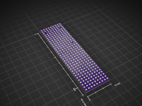
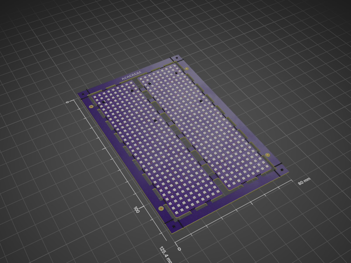
RGB Panel is an open-source printed circuit board by corndog2000, from the corndog2000/RGB-LED-Matrix-Input-Module repository on GitHub. It is a 2-layer board of 80 × 125.4 mm with 932 parts on 716 nets, routed with 5,594 tracks and 758 vias.
It is built around the RP2040, W25Q16JVUXIQ and SK6805-EC14, with the A6H-2101 among its other parts. Its parts include 36 capacitors, 34 resistors, 10 diodes, 8 ICs and 4 fuses. It belongs with the lEDs and displays boards and the RP2040 boards of this library.


| Qty | Value | Footprint | References |
|---|---|---|---|
| 576 | SK6805-EC14 | FootprintLibrary:SK6805-EC14 | N1-0, N1-1, N10-0, N10-1, N100-0, N100-1, N101-0, N101-1, N102-0, N102-1, N103-0, N103-1, N104-0, N104-1, N105-0, N105-1 +560 |
| 220 | NPTH | NPTH | KiKit_MB_10_1, KiKit_MB_10_2, KiKit_MB_10_3, KiKit_MB_10_4, KiKit_MB_11_1, KiKit_MB_11_2, KiKit_MB_11_3, KiKit_MB_11_4, KiKit_MB_12_1, KiKit_MB_12_2, KiKit_MB_12_3, KiKit_MB_12_4, KiKit_MB_13_1, KiKit_MB_13_2, KiKit_MB_13_3, KiKit_MB_13_4 +204 |
| 20 | 100nF | Capacitor_SMD:C_0402_1005Metric | C3-0, C3-1, C4-0, C4-1, C5-0, C5-1, C10-0, C10-1, C11-0, C11-1, C12-0, C12-1, C13-0, C13-1, C14-0, C14-1 +4 |
| 16 | 470 | Resistor_SMD:R_0402_1005Metric | R9-0, R9-1, R10-0, R10-1, R11-0, R11-1, R12-0, R12-1, R13-0, R13-1, R14-0, R14-1, R15-0, R15-1, R16-0, R16-1 |
| 10 | D_TVS | Diode_SMD:D_0402_1005Metric | D1-0, D1-1, D2-0, D2-1, D3-0, D3-1, D4-0, D4-1, D5-0, D5-1 |
| 8 | 10k | Resistor_SMD:R_0402_1005Metric | R2-0, R2-1, R4-0, R4-1, R8-0, R8-1, R24-0, R24-1 |
| 8 | 10uF | Capacitor_SMD:C_0603_1608Metric | C15-0, C15-1, C16-0, C16-1, C17-0, C17-1, C18-0, C18-1 |
| 8 | Fiducial | Fiducial | KiKit_FID_B_1, KiKit_FID_B_2, KiKit_FID_B_3, KiKit_FID_B_4, KiKit_FID_T_1, KiKit_FID_T_2, KiKit_FID_T_3, KiKit_FID_T_4 |
| 6 | -0, -0, -0, -1, -1, -1 | ||
| 4 | 15pF | Capacitor_SMD:C_0402_1005Metric | C1-0, C1-1, C2-0, C2-1 |
| 4 | 1k | Resistor_SMD:R_0402_1005Metric | R1-0, R1-1, R3-0, R3-1 |
| 4 | 1uF | Capacitor_SMD:C_0402_1005Metric | C6-0, C6-1, C8-0, C8-1 |
| 4 | 27 | Resistor_SMD:R_0402_1005Metric | R5-0, R5-1, R6-0, R6-1 |
| 4 | 74AHC125BQ_115 | 74AHC125BQ_115:QFN50P300X250X100-15N | U3-0, U3-1, U4-0, U4-1 |
| 2 | 12.000MHz | Crystal:Crystal_SMD_3225-4Pin_3.2x2.5mm | Y1-0, Y1-1 |
| 2 | 180k | Resistor_SMD:R_0402_1005Metric | R7-0, R7-1 |
| 2 | A6H-2101 | footprints:SW_A6H-2101_OMR | SW1-0, SW1-1 |
| 2 | FH34SRJ-12S-0.5SH_50_ | FH34SRJ-12S-0.5SH_50_:HRS_FH34SRJ-12S-0.5SH_50_ | J2-0, J2-1 |
| 2 | LOGO | InputModule:BY | G***-0, G***-1 |
| 2 | LOGO | InputModule:FW QR | G***-0, G***-1 |
| 2 | LOGO | InputModule:FW OFFICIAL | G***-0, G***-1 |
| 2 | LOGO | InputModule:NC | G***-0, G***-1 |
| 2 | LOGO | InputModule:heart | G***-0, G***-1 |
| 2 | LOGO | InputModule:oshd | G***-0, G***-1 |
| 2 | LOGO | InputModule:SA | G***-0, G***-1 |
| 2 | LOGO | InputModule:QR | G***-0, G***-1 |
| 2 | LOGO | InputModule:CC | G***-0, G***-1 |
| 2 | Polyfuse 200mA | Resistor_SMD:R_1206_3216Metric | F2-0, F2-1 |
| 2 | Polyfuse 600mA | Resistor_SMD:R_1206_3216Metric | F1-0, F1-1 |
| 2 | RP2040 | Package_DFN_QFN:QFN-56-1EP_7x7mm_P0.4mm_EP3.2x3.2mm | U2-0, U2-1 |
| 2 | W25Q16JVUXIQ | InputModule:SON-8-1EP_3x2mm_P0.5mm_EP0.2x1.6mm | U1-0, U1-1 |
The 926 most common of 932 parts.


forrestrae/teensy-sound-sensor-pcb
A KiCad 9.0 carrier board for the Teensy 4.x microcontroller, designed for real-time audio sensing with USB-C Power Delivery input, 4S Li-ion battery management, I2S MEMS microphone, and LED lighting outputs.

Reboot-Codes/clover
Smart fursuit parts made for daily wear to help out your species dysphoria.


Hanqaqa/Easyduino
Easily dive into different PCB KiCad designs of the most popular microcontroller devboards


FrameworkComputer/InputModules
Reference designs and documentation for the Input Module system in the Framework Laptop 16
It measures 80 × 125.4 mm and has 2 copper layers, 0.96 mm thick.
932 parts, built around the RP2040, W25Q16JVUXIQ, SK6805-EC14 and A6H-2101. The full list of its parts is on this page, with links to each part's symbol and footprint where PCBKit's library has them.
From the corndog2000/RGB-LED-Matrix-Input-Module repository on GitHub, at the commit this page was made from: the board is RGB-Panel/RGB-Panel.kicad_pcb and its schematic MicrocontrollerInputModule.kicad_sch. PCBKit opens the board in the browser, with nothing to install.
Its repository states no licence, so its author keeps all rights: ask corndog2000 before reusing the design.