
2 layers304.8 × 170.8 mm

 cookobit/ebf_lamp11
Electrical Blast Furnace (EBF) from GT modpacks 3D-printed lamp
EBF lamp driver circuit is an open-source printed circuit board by cookobit, from the cookobit/ebf_lamp repository on GitHub. It is a 2-layer board of 160 × 80 mm with 28 parts on 22 nets, routed with 91 tracks and 0 vias.
It is built around the IRLZ44N. Its parts include 7 connectors, 6 resistors, 5 capacitors, 2 diodes and 2 transistors. It belongs with the lEDs and displays boards of this library.
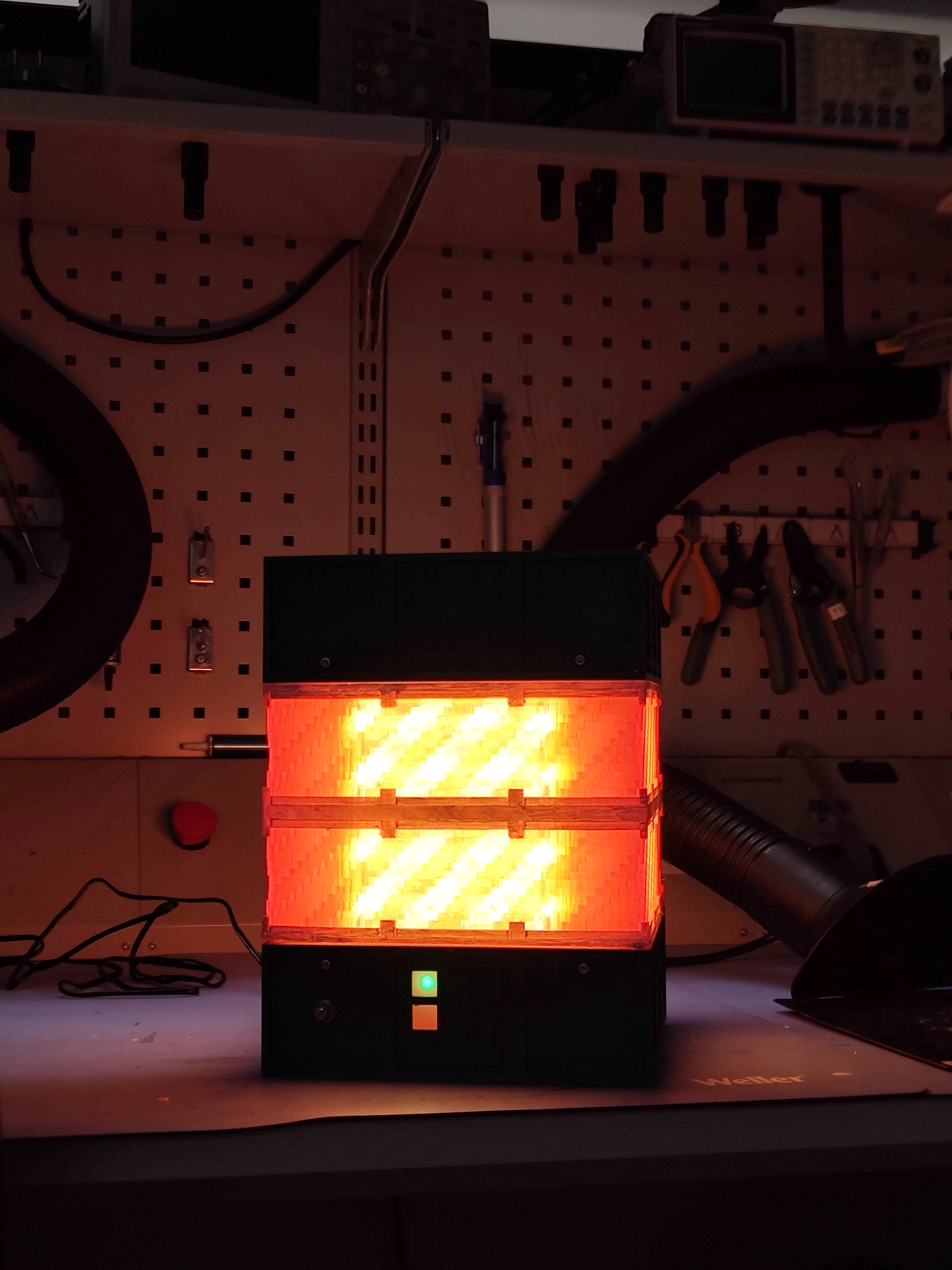
You came after the Electrical Blast Furnace (EBF) from GregTech modpacks, especially GTNH. This repository contains all production files to date, plus special 3D-print files you can print at home and assemble yourself.
IMPORTANT: Current dimensions are 192x192x256 mm for the lamp, change the scale for regular version, since the lamp has mounting holes for M3 screws and other components.
In short, the STLs I made so far, as well as some of the design files and software for ESP32 XIAO module. They are separated in two dedicated folders: firmware and hardware. The firmware was used in the Arduino IDE for flashing the program there, and the hardware was designed in the KiCad, dedicated open-source PCB design software.
The repo won't have a complete support and maintained actively, because of the real life stuff.
Hardware files are licensed under CERN-OHL-P; software is licensed under the MIT License. See the respective directories for full license text.
| Qty | Value | Footprint | References |
|---|---|---|---|
| 3 | 100n | Capacitor_THT:C_Disc_D3.0mm_W2.0mm_P2.50mm | C2, C4, C5 |
| 2 | 100 | Resistor_THT:R_Axial_DIN0207_L6.3mm_D2.5mm_P10.16mm_Horizontal | R3, R4 |
| 2 | 10k | Resistor_THT:R_Axial_DIN0207_L6.3mm_D2.5mm_P10.16mm_Horizontal | R1, R2 |
| 2 | 330 | Resistor_THT:R_Axial_DIN0207_L6.3mm_D2.5mm_P10.16mm_Horizontal | R5, R6 |
| 2 | Conn_01x08_Pin | Connector_PinSocket_2.54mm:PinSocket_1x08_P2.54mm_Vertical | J5, J6 |
| 2 | IRLZ44N | Package_TO_SOT_THT:TO-220-3_Horizontal_TabDown | Q1, Q2 |
| 2 | LED | LED_THT:LED_D5.0mm | D1, D2 |
| 2 | Screw_Terminal_01x02 | TerminalBlock_RND:TerminalBlock_RND_205-00045_1x02_P5.00mm_Horizontal | J1, J2 |
| 1 | 100-470u | Capacitor_THT:CP_Radial_D6.3mm_P2.50mm | C1 |
| 1 | 10u | Capacitor_THT:CP_Radial_D6.3mm_P2.50mm | C3 |
| 1 | Buck-XIAO Screw | TerminalBlock_RND:TerminalBlock_RND_205-00045_1x02_P5.00mm_Horizontal | J4 |
| 1 | R_Potentiometer | Connector_PinHeader_2.54mm:PinHeader_1x03_P2.54mm_Vertical | RV1 |
| 1 | Screw_Terminal_01x03 | TerminalBlock_RND:TerminalBlock_RND_205-00046_1x03_P5.00mm_Horizontal | J7 |
| 1 | Screw_Terminal_01x03 LED Strip | TerminalBlock_RND:TerminalBlock_RND_205-00046_1x03_P5.00mm_Horizontal | J3 |
The 23 most common of 28 parts.


pscrespo/Morpheus-STM32
A small 3D printer controller board for use with a "blue pill" STM32F1 generic board. Inspired on http://reprap.org/wiki/SinapTec


MitchBradley/Esp32PrinterController
PCB design for 3D printer controller using ESP32 processor


robinolejnik/dmx-ledstrip-dimmer-32ch
Arduino Mini and TLC5940 based 32 channel 12V PWM dimmer with DMX512 and RDM support.

Moragor/BatteryAnalyzer_MkII
Updated Version of the battery analyzer, now with constant current
It measures 160 × 80 mm and has 2 copper layers, 1.6 mm thick.
28 parts, built around the IRLZ44N. The full list of its parts is on this page, with links to each part's symbol and footprint where PCBKit's library has them.
From the cookobit/ebf_lamp repository on GitHub, at the commit this page was made from: the board is hardware/EBF_lamp_driver_circuit.kicad_pcb and its schematic hardware/EBF_lamp_driver_circuit.kicad_sch. PCBKit opens the board in the browser, with nothing to install.
Its repository states no licence, so its author keeps all rights: ask cookobit before reusing the design.