Skip to the content
PCBKitNew board
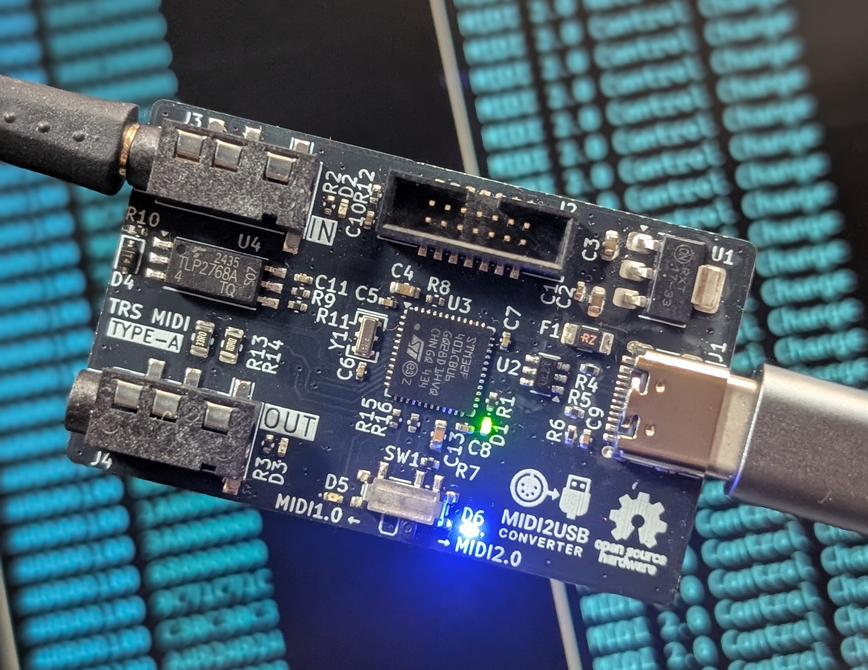
2 layers50 × 30 mmMIDI2USBConv, the printed circuit board in 3D

Open source MIDI2.0 Converter

Size
50 × 30 mm
Copper layers
2
Thickness
1.6 mm
Parts
47
Nets
72
Pads
211
Tracks, vias
590, 109
Pours
2
Routed
Yes
KiCad
KiCad 8.0 (file 20240108)
Created
19 Aug 2025
Updated
2 Mar 2026

Overview

MIDI2USBConv is an open-source printed circuit board by collet-instruments, from the collet-instruments/MIDI2USB-Converter repository on GitHub, published under the MIT licence. It is a 2-layer board of 50 × 30 mm with 47 parts on 72 nets, routed with 590 tracks and 109 vias.

It is built around the STM32F401CBU6, USBLC6-2SC6 and 1N4148WS. Its parts include 16 resistors, 12 capacitors, 6 diodes, 4 ICs and 4 connectors. It belongs with the STM32 boards of this library.

Main components

3

README

README.md

🎹 MIDI2USB Converter

MIDI2USB Logo

CI Code Quality MIT License C C++ STM32 FreeRTOS USB MIDI 2.0

STM32F401-based USB MIDI converter supporting both MIDI 1.0 and MIDI 2.0 protocols.

✨ Features

  • 🎵 Dual Protocol Support: MIDI 1.0 and MIDI 2.0 protocols
  • 🔌 USB Device Classes:
    • MIDI 1.0: Standard USB MIDI Class
    • MIDI 2.0: USB MIDI 2.0 Class with UMP support
  • 🔄 Dynamic Mode Switching: Automatic detection based on SETUP switch
  • 📦 UMP (Universal MIDI Packet): Full support for MIDI 2.0 messaging
  • 🔍 MIDI-CI: MIDI-CI v1.2 support
  • 💡 Visual Feedback: LED status indicators
    • Red LED: USB MIDI 1.0 mode indicator
    • Blue LED: USB MIDI 2.0 mode indicator
  • ⚡ Real-time OS: FreeRTOS-based multitasking
  • 🔗 UART Bridge: Hardware TRS MIDI Type-A (3.5mm jack) interface support

📖 Usage

Using USB MIDI1.0 Mode

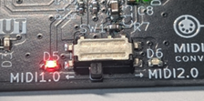
MIDI1.0 mode
  • Switch SETUP (SW1) to MIDI1.0 and connect the USB Type-C port (J1) to a USB host
  • The red LED (D5) will light up
  • MIDI packets received at the MIDI IN port (J3) will be sent to the USB host
  • Similarly, MIDI packets sent from the USB host will be output to the MIDI OUT port (J4)
  • Data transfer status can be monitored via indicator LEDs (D2, D3) for both MIDI IN and MIDI OUT ports

Using USB MIDI2.0 Mode

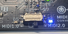
MIDI2.0 mode
  • Switch SETUP (SW1) to MIDI2.0 and connect the USB Type-C port (J1) to a USB host
  • The blue LED (D6) will light up
  • MIDI packets (MIDI1.0 byte stream) received at the MIDI IN port (J3) are converted to USB MIDI2.0 UMP (Universal MIDI Packet) and sent to the USB host
    • At this time, MIDI1.0 Voice Messages are extended to MIDI2.0 Protocol (UMP Message Type 4)
    • Similarly, MIDI2.0 UMP sent from the USB host is converted to MIDI1.0 byte stream and output to the MIDI OUT port (J4)
      • Since MIDI2.0 Protocol sent from the USB host is converted to MIDI1.0 Protocol, some data may be lost
  • Data transfer status can be monitored via indicator LEDs (D2, D3) for both MIDI IN and MIDI OUT ports
  • Some operating systems do not support USB MIDI2.0 drivers, in which case MIDI2.0 mode may not be available. Please use MIDI1.0 mode in such cases.

🔄 Protocol Conversion Rules

MIDI 1.0 → MIDI 2.0 Conversion

The converter performs a 2-stage conversion process:

  1. Stage 1: MIDI 1.0 byte stream → UMP (MIDI 1.0 Protocol)
  2. Stage 2: UMP (MIDI 1.0 Protocol) → UMP (MIDI 2.0 Protocol)

Key transformations:

  • Resolution Enhancement: 7-bit values are scaled up to 16-bit or 32-bit
    • Note velocity: 7-bit → 16-bit (e.g., 127 → ~65024)
    • Control Change values: 7-bit → 32-bit
    • Pitch Bend: 14-bit → 32-bit
  • Message Type: Voice Messages are upgraded to UMP Message Type 4 (MIDI 2.0 Protocol)

MIDI 2.0 → MIDI 1.0 Conversion

Direct conversion from UMP to MIDI 1.0 byte stream:

Key transformations:

  • Resolution Reduction: High-resolution values are scaled down
    • Control values: 32-bit → 7-bit
  • Special handling for Note On velocity 0:
    • In MIDI 2.0, Note On with velocity 0 remains a Note On
    • During conversion, velocity 0 is changed to 1 to prevent unintended Note Off behavior in MIDI 1.0
  • Data Loss: MIDI 2.0-specific features (extended CC, per-note controllers) cannot be represented in MIDI 1.0

Conversion Examples

  • MIDI 1.0 Note On: 90 3C 64 (Ch1, Middle C, Velocity 100) → MIDI 2.0 UMP: 40902C00 32800000 (Velocity ≈ 51200)

  • MIDI 2.0 Note On: Velocity 32768 (50% intensity) → MIDI 1.0: 90 3C 40 (Velocity 64, precision reduced)

⚠️ Caution

  • The IN/OUT terminals of this product are TRS MIDI Type-A only. Do not use other types of cables.
  • Make sure not to confuse IN and OUT connections. Incorrect wiring may cause reverse current and damage your equipment.
  • This product is designed for USB Type-C 5V power supply only. Do not apply any other voltage.
  • The product may be damaged by static electricity. Please handle with proper ESD precautions.
  • Modifications or improper soldering may cause malfunction or accidents.
  • Do not use in environments with high temperature, high humidity, direct sunlight, or condensation.
  • Compatibility with all MIDI devices is not guaranteed.

📜 Disclaimer

  • This product is provided for electronic hobby, educational, and research purposes.
  • It is not a consumer-ready product and has not been certified under any safety standards or regulations (such as PSE, Radio Act certification, CE, UL, etc.).
  • By purchasing and using this product, you agree to the following terms:

Use at Your Own Risk

  • We accept no responsibility for any damage to equipment, personal injury, fire, data loss, or any other loss or accident resulting from the use of this product.

Limitations of Use

  • Do not use this product in industrial equipment, medical devices, safety systems, or any other applications where human life or property may be at risk.
  • Continuous long-term operation or use under heavy loads is not intended.

Modification and Connections

  • We are not responsible for any malfunction or damage caused by modification of this product or connection to unintended devices.

Returns and Warranty

  • If a manufacturing defect is confirmed, we will provide a replacement or refund.
  • No other warranties or guarantees are offered.

⚙️ Modification and Collaboration

  • This product is provided as open hardware.
    You are free to modify, reuse, or build upon the circuit and firmware.
    However, we cannot guarantee the operation or safety of modified versions.

  • We welcome contributions from developers and users who wish to improve the design.
    Please feel free to share feedback, modifications, or enhancement ideas.

🛠️ Build Requirements

  • ARM GCC toolchain (arm-none-eabi-gcc)
  • CMake (3.22 or later)
  • Ninja build system
  • Git (for submodules)

📥 Getting Started

Clone the Repository

bash
git clone --recursive https://github.com/collet-instruments/MIDI2USB-Converter.git
cd MIDI2USB-Converter

# If you already cloned without --recursive, initialize submodules
git submodule init
git submodule update

IDE Integration

VS Code: Use CMake extension for building and debugging with ST-Link.

🔨 Building

Using CMake

bash
# Configure the project
cmake --preset Debug

# Build the firmware
cmake --build --preset Debug

# The output files will be in build/Debug/

Build Configurations

The project supports multiple build configurations:

  • Debug: Development build with debug symbols (default)
  • Release: Optimized build for production (-O2 optimization)
  • RelWithDebInfo: Release build with debug info
  • MinSizeRel: Size-optimized build (-Os optimization)

🧪 Testing

The project includes a comprehensive unit test suite using Unity framework.

Running Tests

bash
# Run all tests
cd test
make test

# Run specific test
make test-mode_manager

# Run tests with coverage
make clean
make COVERAGE=1
make test

✅ Code Quality

Code Formatting

The project uses clang-format for code formatting. Configuration is in .clang-format.

bash
# Format code
clang-format -i Core/Src/*.c Core/Inc/*.h

# Check formatting without modifying files
clang-format --dry-run --Werror Core/Src/*.c Core/Inc/*.h

Static Analysis

bash
# Run cppcheck
cppcheck --enable=warning,style,performance,portability \
  -I Core/Inc \
  Core/Src/

CI/CD

GitHub Actions automatically runs on every push and pull request:

Workflows:
  • ci.yml: Main CI pipeline

    • Builds STM32 firmware
    • Runs all unit tests
    • Uploads firmware artifacts
  • code-quality.yml: Code quality checks

    • Static analysis with cppcheck
    • Code formatting verification with clang-format
  • release.yml: Automated releases

    • Triggers on version tags (v*)
    • Creates GitHub releases with firmware binaries

📁 Project Structure

text
├── Core/               # Application source code
├── Drivers/            # STM32 HAL and CMSIS drivers
├── submodules/         # External dependencies
│   ├── FreeRTOS-Kernel/
│   ├── tinyusb/
│   ├── AM_MIDI2.0Lib/
│   ├── tusb_ump/
│   └── Unity/
├── test/               # Unit tests (Unity framework)
│   ├── src/            # Test source files
│   ├── mock/           # Mock implementations
│   └── include/        # Test headers
├── ci/                 # CI/CD scripts
└── .github/            # CI/CD workflows

📦 Submodules

This project uses the following Git submodules:

SubmoduleRepository URLDescription
FreeRTOS-Kernelhttps://github.com/FreeRTOS/FreeRTOS-Kernel.gitFreeRTOS kernel files only
tinyusbhttps://github.com/hathach/tinyusb.gitAn open source cross-platform USB stack for embedded system
tusb_umphttps://github.com/midi2-dev/tusb_umpUSB MIDI 2.0 tinyUSB Device driver with backwards compatibility to USB MIDI 1.0
AM_MIDI2.0Libhttps://github.com/midi2-dev/AM_MIDI2.0LibA MIDI 2.0 C++ Library
Unityhttps://github.com/ThrowTheSwitch/Unity.gitSimple unit testing for C

🔧 Hardware

🎛️ Microcontroller

  • MCU: STM32F401CBU6 (ARM Cortex-M4, 84MHz)
  • Flash: 256KB
  • RAM: 64KB

🔌 Interfaces

  • USB: Full-Speed USB 2.0 (12Mbps)
  • UART: MIDI serial interface (31.25 kbaud)
    • TX: PA2 (USART2_TX)
    • RX: PA3 (USART2_RX)
  • DEBUG: ST-Link support (J2 connector)

📍 GPIO Pins

  • Mode Selection: PA5 (SETUP pin)
    • High: USB MIDI 2.0 mode
    • Low: USB MIDI 1.0 mode
  • LEDs:
    • M1LED: PA4 - USB MIDI 1.0 mode indicator
    • M2LED: PA6 - USB MIDI 2.0 mode indicator

⚡ Power

  • Powered via USB (5V)
  • 3.3V internal operation

💻 Development

Running Tests Locally

bash
# Quick test before pushing
./ci/test-ci-locally.sh

# Install optional CI tools
./ci/install-ci-tools.sh

Debugging

  1. VS Code: Use CMake extension and ST-Link for debugging
  2. OpenOCD: Manual debugging with GDB
  • Connect the J2 connector (NRST, SYS_SWCLK, SYS_SWDIO) to ST-Link for debugging. USART1 is also available for printf debugging.

🤝 Contributing

We welcome contributions! Please see CONTRIBUTING.md for details on:

  • How to submit issues
  • How to submit pull requests
  • Code style guidelines
  • Development setup

📜 Code of Conduct

This project adheres to a Code of Conduct. By participating, you are expected to uphold this code. Please see CODE_OF_CONDUCT.md for details.

📄 License

This project is licensed under the MIT License - see the LICENSE file for details.

Hardware Design: All hardware design files including schematics, PCB layouts, and manufacturing files in the hardware/ directory are also covered under the same MIT License.

Third-party Licenses

This project uses the following open-source libraries:

  • FreeRTOS-Kernel: MIT License
  • TinyUSB: MIT License
  • AM_MIDI2.0Lib: MIT License
  • Unity Test Framework: MIT License
  • STM32 HAL Drivers: BSD 3-Clause License (STMicroelectronics)

👥 Authors and Acknowledgments

  • USB MIDI 2.0 implementation based on TinyUSB and AM_MIDI2.0Lib
  • STM32 HAL drivers by STMicroelectronics
  • Special thanks to all contributors

💬 Support

For questions and support:

  • Open an issue on GitHub
  • Check existing issues and discussions
  • See documentation in the repository

📝 Copyright

Copyright © 2025 Collet Instruments. All rights reserved.

Parts

47
QtyValueFootprintReferences
70.1uCapacitor_SMD:C_0402_1005MetricC1, C5, C6, C7, C8, C10, C11
31.5kResistor_SMD:R_0402_1005MetricR9, R15, R16
31kResistor_SMD:R_0402_1005MetricR1, R2, R3
3GreenLED_SMD:LED_0402_1005MetricD1, D2, D3
2100Resistor_SMD:R_0402_1005MetricR11, R12
210kResistor_SMD:R_0402_1005MetricR7, R8
210uCapacitor_SMD:C_0603_1608MetricC2, C3
25.1kResistor_SMD:R_0402_1005MetricR4, R5
2AudioJack4Connector_Audio:Jack_3.5mm_PJ320D_HorizontalJ3, J4
110Resistor_SMD:R_0805_2012MetricR14
11MResistor_SMD:R_0402_1005MetricR6
11N4148WSDiode_SMD:D_SOD-323D4
12.2uCapacitor_SMD:C_0603_1608MetricC13
1220Resistor_SMD:R_0402_1005MetricR10
133Resistor_SMD:R_0805_2012MetricR13
14.7nFCapacitor_SMD:C_0402_1005MetricC9
14.7uCapacitor_SMD:C_0603_1608MetricC4
16V 2.0AFuse:Fuse_1206_3216MetricF1
18MHzCrystal:Resonator_SMD_Murata_CSTxExxV-3Pin_3.0x1.1mmY1
1BlueLED_SMD:LED_0402_1005MetricD6
1Conn_ST_STDC14STDC14_SMD:STDC14_SMDJ2
1LOGOlogo:midi2usb_logoG***
1NCP1117-3.3_SOT223Package_TO_SOT_SMD:SOT-223-3_TabPin2U1
1RedLED_SMD:LED_0402_1005MetricD5
1STM32F401CBU6Package_DFN_QFN:QFN-48-1EP_7x7mm_P0.5mm_EP5.6x5.6mmU3
1SW_SPDT_312Button_Switch_SMD:SW_SPDT_PCM12SW1
1TLP2768A(D4-TP,E(TPackage_SO:SO-6L_10x3.84mm_P1.27mmU4
1USBLC6-2SC6Package_TO_SOT_SMD:SOT-23-6U2
1USB_C_Receptacle_USB2.0_16PConnector_USB:USB_C_Receptacle_G-Switch_GT-USB-7010ASVJ1

The 46 most common of 47 parts.

Questions

How big is the MIDI2USBConv PCB?

It measures 50 × 30 mm and has 2 copper layers, 1.6 mm thick.

What parts does the MIDI2USBConv use?

47 parts, built around the STM32F401CBU6, USBLC6-2SC6 and 1N4148WS. The full list of its parts is on this page, with links to each part's symbol and footprint where PCBKit's library has them.

Where can I download the MIDI2USBConv KiCad files?

From the collet-instruments/MIDI2USB-Converter repository on GitHub, at the commit this page was made from: the board is hardware/kicad8/MIDI2USBConv.kicad_pcb and its schematic hardware/kicad8/MIDI2USBConv.kicad_sch. PCBKit opens the board in the browser, with nothing to install.

Can I use the MIDI2USBConv design in my own project?

Its repository publishes it under the MIT licence: you may reuse it on that licence's terms (keep the author's notice, and for a copyleft licence share your changes alike).

Similar boards

  • 4 layers90.3 × 94.6 mmThermalV3, the printed circuit board in 3D

    ThermalV3

    moro696/thermal_camera

    A diy thermal camera based on a Flir Lepton 3.5 sensor

    126 parts7
  • 2 layers300 × 100.8 mmJay EC65, the printed circuit board in 3D

    Jay EC65

    alabahuy/zed65

    custom bakeneko65 pcb

    165 partsMIT
  • 2 layers134 × 88 mmTulipcc, the printed circuit board in 3D

    Tulipcc

    shorepine/tulipcc

    The Tulip Creative Computer and AMYboard - portable Python synthesizers

    103 parts978
  • 2 layers132 × 90.7 mmDao choc ble right, the printed circuit board in 3D

    Dao choc ble right

    Mposiblee/Zireael

    The keyboard is based on Dao Chok BLE. The locations of components on the board have been changed, space for the battery has been added, and the thumb cluster has also been changed.

    79 parts42CERN-OHL-P-2.0
  • 4 layers66.4 × 66.4 mmRera, the printed circuit board in 3D

    Rera

    fdiwth/tvc-drone

    This repository contains the documentation, hardware designs, and source code for a Thrust Vector Control (TVC) drone.

    140 parts34GPL-3.0
  • 4 layers40 × 58.5 mmPicoFox PCB, the printed circuit board in 3D

    PicoFox PCB

    ai6ym/PicoFox

    The open source fox transmitter.

    143 parts16
  • 4 layers71.9 × 94 mmThumbdeck right, the printed circuit board in 3D

    Thumbdeck right

    neuman/gripster

    thumbdeck — wireless split thumb keyboard (nRF52840 + ZMK, BLE split, i8+-inspired). Layout converged & graded PASS.

    114 parts11Apache-2.0
  • 2 layers102.4 × 102.4 mmGenerator 5351 rect sine, the printed circuit board in 3D

    Generator 5351 rect sine

    MR-DOS/generator_5351_rect_sine

    Rectangular and sine generator with Si5351 working up to 200 MHz

    284 parts6GPL-3.0