2 layers56 × 65 mm
SeaTalk1
dotnet/iot
This repo includes .NET Core implementations for various IoT boards, chips, displays and PCBs.
24 parts2.4kMIT

 colinRawlings/yiF1
connecting an action camera to a EFs STM lens
Ard shield is an open-source printed circuit board by colinRawlings, from the colinRawlings/yiF repository on GitHub. It is a 2-layer board of 97.3 × 54.9 mm with 24 parts on 47 nets, routed with 226 tracks and 6 vias.
Its parts include 8 connectors, 6 switches, 3 resistors, 2 capacitors and 2 ICs.
a foolish combination of action cameras and SLR lenses
This is a project seeking to replace an action cameras fisheye lens with one of the low cost plastic bodied EFs STM zoom lenses from Canon. Ideally this combines the action camera's high frame rates (HD at 240 frames/second) with the lens' zoom, depth of field control and active image stabilisation. Some example footage is here:
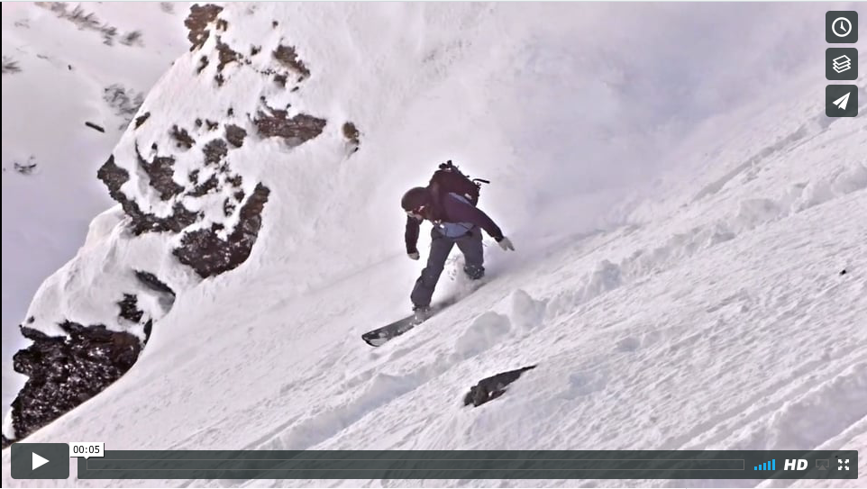
The lens is controlled via an Arduino micro and a Yi 4k+ was used for the action camera. Via the arduino the lens' focus, aperture and image stabilisation motors can be controlled. The housing is 3D printed and a commlite EF-EOSM adaptor is used for mounting the lens.
For video monitoring the Yi's in-built display combined with an optical viewfinder (the kinotehnik LCDVF 3/2) or an external monitor (smartphone or the ikan VL35) was used.
The system was tested with several of the EFs STM lenses (10-18 mm, 18-135 mm f3.5 and 55-250 mm f4) and a sigma 35 mm f1.4. The system exhibits a roughly 3x crop sensor, this amplifies the available travel of the image stabiliser, increases the reach of the lens and improves the depth of field control.
So far nothing bad has happened to the lenses however:
You can apparently burn the aperture motor in Canon lenses quite easily.
I take no responsibility for any damage caused by the things in this repo.
The starting point for this work was this article:
https://pickandplace.wordpress.com/2011/10/05/canon-ef-s-protocol-and-electronic-follow-focus/
from here I used a Saleae logic analyser to record the conversations between the lenses and a 650D. These were then analysed in Matlab since in particular I needed the command to start the image stabilisation motor and activate the manual focus ring (the STM lenses are “focus by wire”).
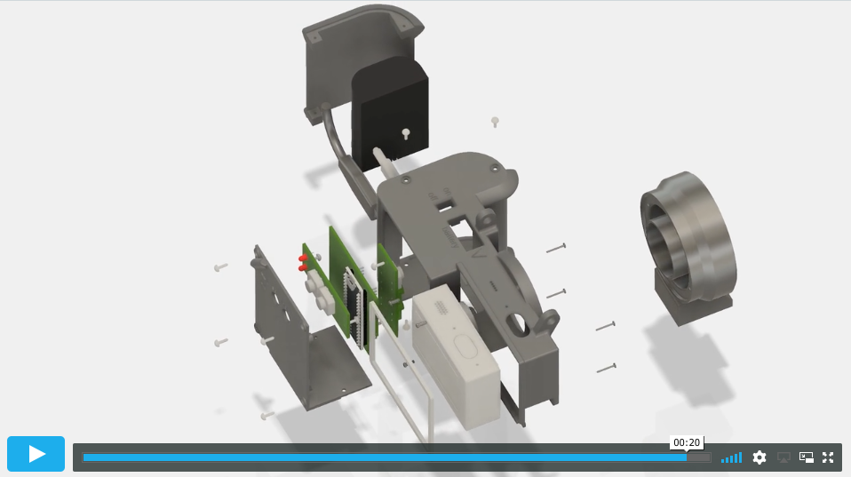
This comes in several parts
The cad was done in Fusion (free for the first year). The assembly is here: http://a360.co/2sxdWEE
the stl files for printing are in cad/fab. They are only suitable for selective laser sintering or HP jet fusion of nylon. I used 3Dhubs.com to find a nearby printer.
The electronics design was done in kicad. Note the arduino can control the power to the lens. The entire lens is switch off after each movement of the aperture motor rather than relying on the motor off command being successfully received. The gerber files are in elec/fab. I eventually settled on powering the system with an LP-E6 camera battery.
| Qty | Value | Footprint | References |
|---|---|---|---|
| 2 | 470 | Resistors_ThroughHole:Resistor_Horizontal_RM7mm | R2, R3 |
| 1 | 0.1u | Capacitors_ThroughHole:C_Disc_D3_P2.5 | C1 |
| 1 | 1k | Resistors_ThroughHole:Resistor_Horizontal_RM7mm | R1 |
| 1 | ARDUINO_MICRO_SHIELD | arduino_micro_shield:ARDUINO_MICRO_SHIELD | U2 |
| 1 | CONN_Voltmeter | Pin_Headers:Pin_Header_Straight_1x02 | P5 |
| 1 | CONN_bat | Pin_Headers:Pin_Header_Straight_1x02 | P1 |
| 1 | CONN_if1_if1 | Socket_Strips:Socket_Strip_Straight_2x03 | P4 |
| 1 | CONN_if1_main | Pin_Headers:Pin_Header_Straight_2x03 | P6 |
| 1 | CONN_if2_if2 | Pin_Headers:Pin_Header_Straight_1x04 | P2 |
| 1 | CONN_if2_main | Socket_Strips:Socket_Strip_Straight_1x04 | P3 |
| 1 | CONN_lensX02 | Socket_Strips:Socket_Strip_Straight_1x02 | P8 |
| 1 | CONN_lensX05 | Socket_Strips:Socket_Strip_Straight_1x05 | P7 |
| 1 | CP | Capacitors_ThroughHole:C_Rect_L7_W2_P5 | C2 |
| 1 | LM2937 | Power_Integrations:TO-220 | U1 |
| 1 | Led_err | LEDs:LED-3MM | D1 |
| 1 | Led_status | LEDs:LED-3MM | D2 |
| 1 | Q_PNP_EBC | Transistors_OldSowjetAera:OldSowjetaera_Transistor_Type-II_BigPads | Q1 |
| 1 | SAv | Buttons_Switches_ThroughHole:SW_PUSH-12mm | SW3 |
| 1 | Sbat | Pin_Headers:Pin_Header_Straight_1x02 | SW4 |
| 1 | Sminus | Buttons_Switches_ThroughHole:SW_PUSH-12mm | SW2 |
| 1 | Splus | Buttons_Switches_ThroughHole:SW_PUSH-12mm | SW1 |
| 1 | Srecall | Buttons_Switches_ThroughHole:SW_PUSH-12mm | SW6 |
| 1 | Sset | Buttons_Switches_ThroughHole:SW_PUSH-12mm | SW5 |
dotnet/iot
This repo includes .NET Core implementations for various IoT boards, chips, displays and PCBs.

pascallanger/DIY-Multiprotocol-TX-Module
Multiprotocol TX Module (or MULTI-Module) is a 2.4GHz transmitter module which controls many different receivers and models.


rusefi/rusefi
rusefi - GPL internal combustion engine control unit

DraftShift/StealthChanger
Tool changing system for Vorons and other front mount printer motion systems, not just stealthburner.

VoronDesign/Voron-Hardware
Cool Hardware designed by the Voron Design group

hackclub/OnBoard
💡 Join 1,000 teenagers and make your first PCB with a $100 grant!

It measures 97.3 × 54.9 mm and has 2 copper layers, 1.6 mm thick.
24 parts. The full list of its parts is on this page, with links to each part's symbol and footprint where PCBKit's library has them.
From the colinRawlings/yiF repository on GitHub, at the commit this page was made from: the board is pcb/ard_shield/ard_shield.kicad_pcb. PCBKit opens the board in the browser, with nothing to install.
Its repository states no licence, so its author keeps all rights: ask colinRawlings before reusing the design.