2 layers300 × 200 mm
Model 150
Julesc013/project-carbon
Hardware and software for custom CPUs, FPUs, and computer systems.
377 parts

 codorjan/duart3
DUART Serial Board Designed For RC2014
Duart is an open-source printed circuit board by codorjan, from the codorjan/duart repository on GitHub, published under the CC-BY-SA-4.0 licence. It is a 2-layer board of 99.1 × 49.9 mm with 39 parts on 99 nets, routed with 831 tracks and 70 vias.
It is built around the 74HCT00D, 74HCT688D and 74HCT74D. Its parts include 7 capacitors, 7 connectors, 4 resistors, 4 ICs and 1 switch. It belongs with the interfaces and adapters boards of this library.


This is an XR88C681-based serial interface card designed for the RC2014 microcomputer system. This provides two serial interfaces to an RC2014 system in addition to a 16-bit counter/timer and several general-purpose input and output lines.
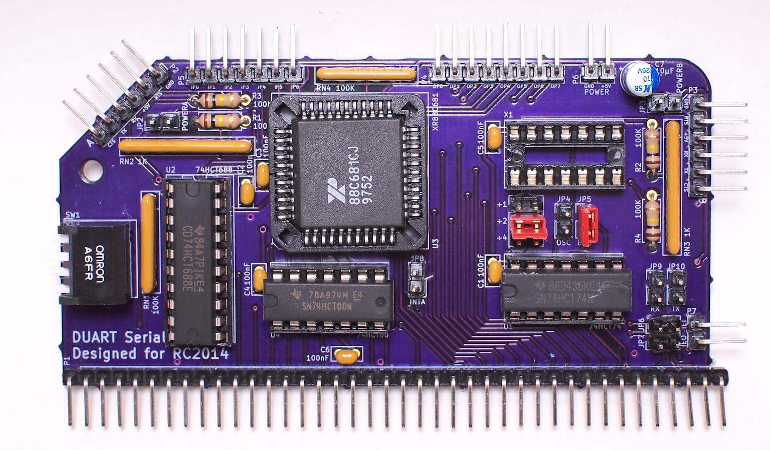
The board has undergone limited testing with the SCM driver written by Colin MacArthur for Tadeusz Pycio's XR88C681 board (and it should be fully software compatible with it).
A driver has been incorporated into the dev branch of RomWBW. This is not currently built into the standard RC2014 ROM but is available in the RCZ80_duart configuration.
Until this is properly documented, refer to the schematic.
The values and types of most components are not critical. Capacitors C1-C6 (100nF, MLCC) are power bypass/decoupling capacitors for each IC and C7 (10µF, electrolytic) provides additional transient decoupling for the DUART itself. RN1 and RN4 (100kΩ) are bussed resistor networks intended to act as pull-ups for the chip select logic (RN1) and to prevent the general purpose inputs (and IM2-specific interrupt lines) from floating (RN4). RN2 and RN3 (1kΩ) are isolated resistor networks intended to provide short-circuit protection to the serial I/O lines. R1 and R2 (100kΩ) pull the serial receive input lines up to their idle state. R3 and R4 (100kΩ) pull the serial /CTS input lines down to their active state.
Oscillator X1 and capacitor C5 are optional in a standard RC2014 system with a 7.3728MHz clock. In this case JP5 should be closed and pins 3 and 4 (CLKDIV2) of JP1 should be bridged with jumpers to provided the DUART with its expected 3.6864MHz clock.
Copyright 2019-2020 Chris Odorjan
This work is licensed under a Creative Commons Attribution-ShareAlike 4.0 International License.
| Qty | Value | Footprint | References |
|---|---|---|---|
| 6 | 100nF | Capacitor_THT:C_Rect_L4.6mm_W2.0mm_P2.50mm_MKS02_FKP02 | C1, C2, C3, C4, C5, C6 |
| 4 | 100K | Resistor_THT:R_Axial_DIN0207_L6.3mm_D2.5mm_P7.62mm_Horizontal | R1, R2, R3, R4 |
| 2 | 100K | Resistor_THT:R_Array_SIP6 | RN1, RN4 |
| 2 | 1K | Resistor_THT:R_Array_SIP8 | RN2, RN3 |
| 1 | 10µF | Capacitor_THT:CP_Radial_D5.0mm_P2.00mm | C7 |
| 1 | 74HCT00 | Package_DIP:DIP-14_W7.62mm_Socket | U4 |
| 1 | 74HCT688 | Package_DIP:DIP-20_W7.62mm_Socket | U2 |
| 1 | 74HCT74 | Package_DIP:DIP-14_W7.62mm_Socket | U1 |
| 1 | BUSCLK | Connector_PinHeader_2.54mm:PinHeader_1x02_P2.54mm_Vertical | JP5 |
| 1 | CLKIN | Connector_PinHeader_2.54mm:PinHeader_2x03_P2.54mm_Vertical | JP1 |
| 1 | IEI | Connector_PinHeader_2.54mm:PinHeader_1x02_P2.54mm_Vertical | JP6 |
| 1 | IEO | Connector_PinHeader_2.54mm:PinHeader_1x02_P2.54mm_Vertical | JP7 |
| 1 | IEO/IEI | Connector_PinHeader_2.54mm:PinHeader_1x02_P2.54mm_Vertical | P7 |
| 1 | INPUT | Connector_PinHeader_2.54mm:PinHeader_1x07_P2.54mm_Vertical | P5 |
| 1 | OSCCLK | Connector_PinHeader_2.54mm:PinHeader_1x02_P2.54mm_Vertical | JP4 |
| 1 | OUTPUT | Connector_PinHeader_2.54mm:PinHeader_1x08_P2.54mm_Vertical | P4 |
| 1 | Oscillator | Package_DIP:DIP-14_W7.62mm_Socket | X1 |
| 1 | POWER | Connector_PinHeader_2.54mm:PinHeader_1x02_P2.54mm_Vertical | P6 |
| 1 | POWERA | Connector_PinHeader_2.54mm:PinHeader_1x02_P2.54mm_Vertical | JP2 |
| 1 | POWERB | Connector_PinHeader_2.54mm:PinHeader_1x02_P2.54mm_Vertical | JP3 |
| 1 | RC2014_STANDARD_DEV_39 | Connector_PinHeader_2.54mm:PinHeader_1x39_P2.54mm_Vertical | P1 |
| 1 | RXBUS | Connector_PinHeader_2.54mm:PinHeader_1x02_P2.54mm_Vertical | JP9 |
| 1 | SERIALA | Connector_PinHeader_2.54mm:PinHeader_1x06_P2.54mm_Vertical | P2 |
| 1 | SERIALB | Connector_PinHeader_2.54mm:PinHeader_1x06_P2.54mm_Vertical | P3 |
| 1 | Switch_DIP_4 | Button_Switch_THT:SW_DIP_SPSTx04_Piano_10.8x11.72mm_W7.62mm_P2.54mm | SW1 |
| 1 | TXBUS | Connector_PinHeader_2.54mm:PinHeader_1x02_P2.54mm_Vertical | JP10 |
| 1 | XR88C681-PLCC | Package_LCC:PLCC-44_THT-Socket | U3 |
| 1 | ~INTA | Connector_PinHeader_2.54mm:PinHeader_1x02_P2.54mm_Vertical | JP8 |
The 38 most common of 39 parts.
It measures 99.1 × 49.9 mm and has 2 copper layers, 1.6 mm thick.
39 parts, built around the 74HCT00D, 74HCT688D and 74HCT74D. The full list of its parts is on this page, with links to each part's symbol and footprint where PCBKit's library has them.
From the codorjan/duart repository on GitHub, at the commit this page was made from: the board is duart.kicad_pcb. PCBKit opens the board in the browser, with nothing to install.
Its repository publishes it under the CC-BY-SA-4.0 licence: you may reuse it on that licence's terms (keep the author's notice, and for a copyleft licence share your changes alike).
Julesc013/project-carbon
Hardware and software for custom CPUs, FPUs, and computer systems.

michaelkamprath/minimal-64x4-expansion-cards
A set of expansion boards for the Minimal 64x4 Home Computer


electrified/rc2014-ym2149
KiCad schematics and gerbers for a YM sound card for the RC2014. See it in action here: https://www.youtube.com/watch?v=-iLwi9FagFE


polpo/imagescribbler
A Clone of Apple's ImageWriter II/LQ LocalTalk Option card