2 layers75 × 20 mm

 codeThatThinks/autotank-led-hw
A CANbus-enabled LED and GPIO controller -- PCB design files
Led controller is an open-source printed circuit board by codeThatThinks, from the codeThatThinks/autotank-led-hw repository on GitHub, published under the MIT licence. It is a 2-layer board of 80 × 60 mm with 86 parts on 50 nets, routed with 380 tracks and 132 vias.
It is built around the ISO1042BQDWVQ1, ADG3308BRUZ and DMN3053L-7, with the SMDA24C among its other parts. Its parts include 15 capacitors, 15 connectors, 14 resistors, 7 diodes and 4 ICs. It belongs with the interfaces and adapters boards and the STM32 boards of this library.


A CANbus-enabled LED and GPIO controller -- PCB design files
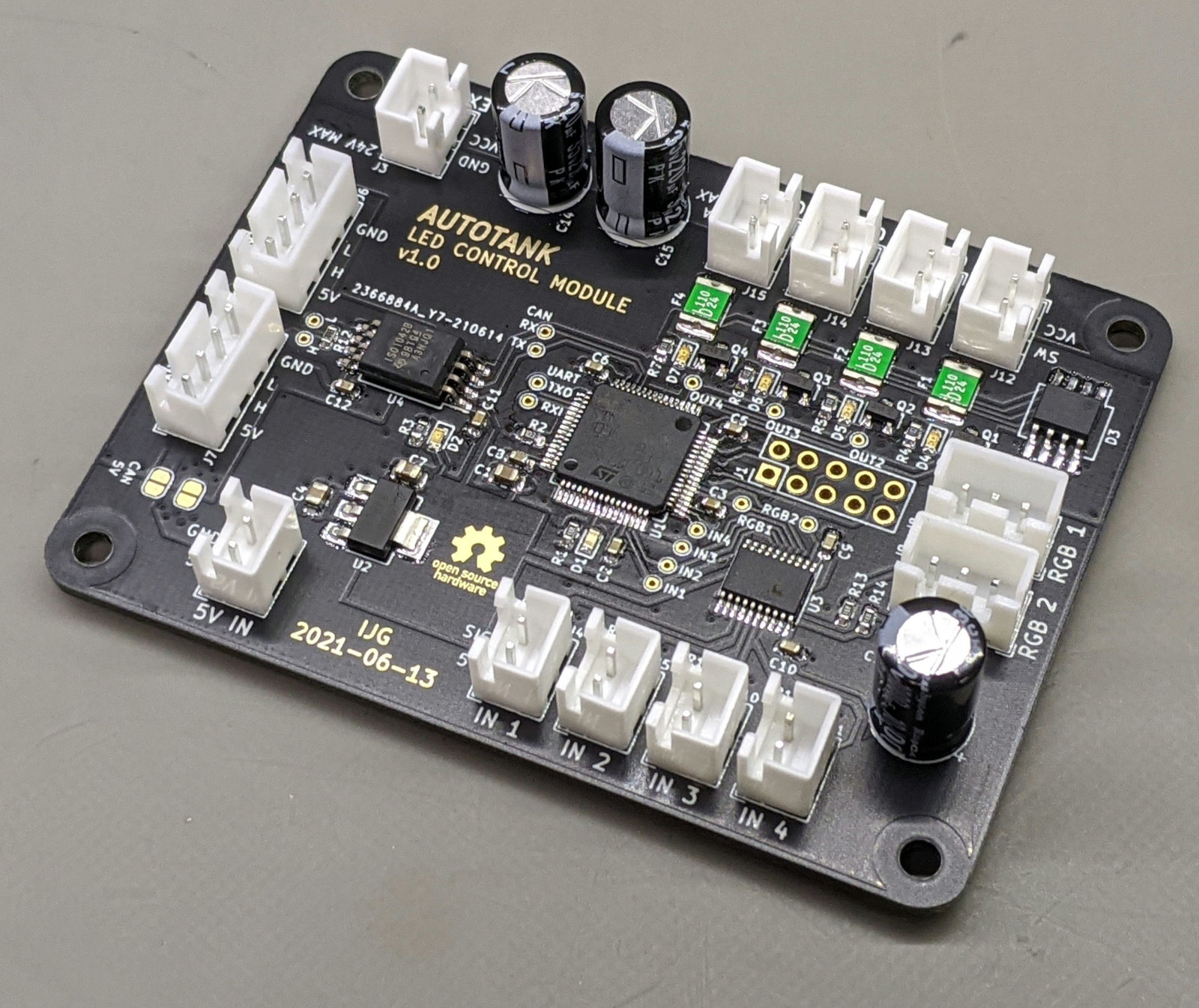
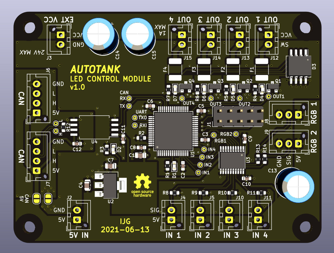
The controller listens for messages on the CANbus and drives two addressable RGB LED strips and four general-purpose open-collector outputs. It also monitors four general-purpose inputs and can send CANbus messages or change outputs in response to events.
The outputs are rated for 1A each and are intended to drive LED lights, such as headlights, tail lights, etc. The inputs are active-high and intended for body sensors and switches, such as a door switch.
| Qty | Value | Footprint | References |
|---|---|---|---|
| 9 | 0.1u | Capacitor_SMD:C_0603_1608Metric | C2, C3, C5, C6, C8, C9, C10, C11, C12 |
| 5 | 10K | Resistor_SMD:R_0603_1608Metric | R2, R8, R9, R10, R11 |
| 5 | 1K | Resistor_SMD:R_0603_1608Metric | R3, R4, R5, R6, R7 |
| 4 | 1.1A | Fuse:Fuse_1812_4532Metric_Castellated | F1, F2, F3, F4 |
| 4 | DMN3053L | Package_TO_SOT_SMD:SOT-23 | Q1, Q2, Q3, Q4 |
| 4 | MountingHole | MountingHole:MountingHole_3.2mm_M3 | H1, H2, H3, H4 |
| 4 | RED | LED_SMD:LED_0603_1608Metric | D4, D5, D6, D7 |
| 3 | 330 | Resistor_SMD:R_0603_1608Metric | R1, R13, R14 |
| 2 | 10u | Capacitor_SMD:C_0805_2012Metric | C4, C7 |
| 2 | 220u | Capacitor_THT:CP_Radial_D8.0mm_P3.50mm | C14, C15 |
| 2 | CAN | Connector_JST:JST_XH_B4B-XH-AM_1x04_P2.50mm_Vertical | J6, J7 |
| 2 | SolderJumper_2_Open | Jumper:SolderJumper-2_P1.3mm_Open_RoundedPad1.0x1.5mm | JP2, JP3 |
| 1 | +5V | Connector_JST:JST_XH_B2B-XH-AM_1x02_P2.50mm_Vertical | J2 |
| 1 | 1000u | Capacitor_THT:CP_Radial_D8.0mm_P3.50mm | C13 |
| 1 | 120 | Resistor_SMD:R_0603_1608Metric | R12 |
| 1 | 4.7u | Capacitor_SMD:C_0805_2012Metric | C1 |
| 1 | ADG3308BRUZ | Package_SO:TSSOP-20_4.4x6.5mm_P0.65mm | U3 |
| 1 | AZ1117-3.3 | Package_TO_SOT_SMD:SOT-223-3_TabPin2 | U2 |
| 1 | BLUE | LED_SMD:LED_0603_1608Metric | D1 |
| 1 | GREEN | LED_SMD:LED_0603_1608Metric | D2 |
| 1 | H | TestPoint:TestPoint_THTPad_D1.0mm_Drill0.5mm | TP16 |
| 1 | IN1 | TestPoint:TestPoint_THTPad_D1.0mm_Drill0.5mm | TP12 |
| 1 | IN1 | Connector_JST:JST_XH_B2B-XH-AM_1x02_P2.50mm_Vertical | J4 |
| 1 | IN2 | TestPoint:TestPoint_THTPad_D1.0mm_Drill0.5mm | TP13 |
| 1 | IN2 | Connector_JST:JST_XH_B2B-XH-AM_1x02_P2.50mm_Vertical | J5 |
| 1 | IN3 | Connector_JST:JST_XH_B2B-XH-AM_1x02_P2.50mm_Vertical | J10 |
| 1 | IN3 | TestPoint:TestPoint_THTPad_D1.0mm_Drill0.5mm | TP14 |
| 1 | IN4 | TestPoint:TestPoint_THTPad_D1.0mm_Drill0.5mm | TP15 |
| 1 | IN4 | Connector_JST:JST_XH_B2B-XH-AM_1x02_P2.50mm_Vertical | J11 |
| 1 | ISO1042BQDWV | Package_SO:SOIC-8_7.5x5.85mm_P1.27mm | U4 |
| 1 | L | TestPoint:TestPoint_THTPad_D1.0mm_Drill0.5mm | TP17 |
| 1 | OUT1 | Connector_JST:JST_XH_B2B-XH-AM_1x02_P2.50mm_Vertical | J12 |
| 1 | OUT1 | TestPoint:TestPoint_THTPad_D1.0mm_Drill0.5mm | TP4 |
| 1 | OUT2 | Connector_JST:JST_XH_B2B-XH-AM_1x02_P2.50mm_Vertical | J13 |
| 1 | OUT2 | TestPoint:TestPoint_THTPad_D1.0mm_Drill0.5mm | TP5 |
| 1 | OUT3 | TestPoint:TestPoint_THTPad_D1.0mm_Drill0.5mm | TP6 |
| 1 | OUT3 | Connector_JST:JST_XH_B2B-XH-AM_1x02_P2.50mm_Vertical | J14 |
| 1 | OUT4 | Connector_JST:JST_XH_B2B-XH-AM_1x02_P2.50mm_Vertical | J15 |
| 1 | OUT4 | TestPoint:TestPoint_THTPad_D1.0mm_Drill0.5mm | TP7 |
| 1 | RGB1 | Connector_JST:JST_XH_B3B-XH-AM_1x03_P2.50mm_Vertical | J8 |
| 1 | RGB1 | TestPoint:TestPoint_THTPad_D1.0mm_Drill0.5mm | TP8 |
| 1 | RGB2 | TestPoint:TestPoint_THTPad_D1.0mm_Drill0.5mm | TP9 |
| 1 | RGB2 | Connector_JST:JST_XH_B3B-XH-AM_1x03_P2.50mm_Vertical | J9 |
| 1 | RX | TestPoint:TestPoint_THTPad_D1.0mm_Drill0.5mm | TP10 |
| 1 | RXI | TestPoint:TestPoint_THTPad_D1.0mm_Drill0.5mm | TP2 |
| 1 | SMDA24C | Package_SO:SO-8_5.3x6.2mm_P1.27mm | D3 |
| 1 | STM32F303RETx | Package_QFP:LQFP-64_10x10mm_P0.5mm | U1 |
| 1 | SWD | Connector_PinHeader_2.54mm:PinHeader_2x05_P2.54mm_Vertical | J1 |
| 1 | TX | TestPoint:TestPoint_THTPad_D1.0mm_Drill0.5mm | TP11 |
| 1 | TXO | TestPoint:TestPoint_THTPad_D1.0mm_Drill0.5mm | TP1 |
| 1 | VCC | Connector_JST:JST_XH_B2B-XH-AM_1x02_P2.50mm_Vertical | J3 |
The 85 most common of 86 parts.
It measures 80 × 60 mm and has 2 copper layers, 1.6 mm thick.
86 parts, built around the ISO1042BQDWVQ1, ADG3308BRUZ, DMN3053L-7 and SMDA24C. The full list of its parts is on this page, with links to each part's symbol and footprint where PCBKit's library has them.
From the codeThatThinks/autotank-led-hw repository on GitHub, at the commit this page was made from: the board is kicad/led-controller.kicad_pcb. PCBKit opens the board in the browser, with nothing to install.
Its repository publishes it under the MIT licence: you may reuse it on that licence's terms (keep the author's notice, and for a copyleft licence share your changes alike).

ManchesterStingerMotorsports/johnson-node
Fully modular CAN node hardware and firmware libraries


MKesenheimer/fault-injection-library
Python library to perform fault-injection attacks on microcontrollers

