2 layers51 × 32 mm
LipoGardenLight
codesqueak/SmallElectronicsProjects
A collection of small projects that can be grouped together
14 parts1

 codesqueak/SmallElectronicsProjects1
A collection of small projects that can be grouped together
Z80Breakout is an open-source printed circuit board by codesqueak, from the codesqueak/SmallElectronicsProjects repository on GitHub. It is a 2-layer board of 58 × 60 mm with 9 parts on 40 nets, routed with 116 tracks and 2 vias.
Its parts include 3 connectors and 1 IC.
Keywords: Garden light, solar light, LED, solar, circuit, QX5252F, oshpark, jlcpcb
I have a number of post type solar garden lamps, with small circular solar cells at the top. These suffer from a number of problems:
I decided to see if it was possible to replace the electronics package with something that would address the issues:
After looking at and testing various designs / component values I found the following configuration to be optimal.
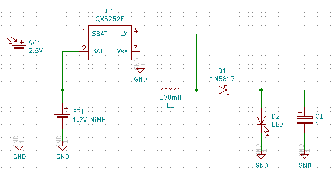
| Component | Value | Comment |
|---|---|---|
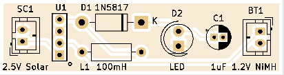
| QX5252F | TO-94 | Datasheet |
| Solar Cell | 2.5V | Select something that will supply adequate power in winter |
| Inductor | 100µH | Alter this values to control the available current |
| Ni-MH Battery | 1.2V | Select something with adequate storage - 1900mAh Ni-MH Eneloop's seem to do the job but overspec'd |
| Diode | 1N5817 | Anything with a low voltage drop will do |
| LED | 20mA / 17500 mCd | Nice and bright with good coverage. Obtained some from Kitronik |
| Capacitor | 1μF | Electrolytic. Serves to increase brightness noticeably but uses more power. Useful for stablizing power for self colour changing LED's |
Note: The capacitor is optional and is only essential when you use colour changing LED's. If you just want to change the brightness, change the inductor.
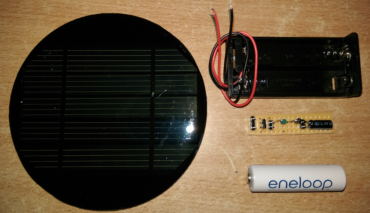
The circuit can be implemented on a small piece of Vero-board. This is small enough to fit within the space taken by one AA cell. Closed dual AA cell battery holders are common and cheap to obtain from eBay, thus solving the protective environment issue.
The battery holder is then affixed onto the base of the solar cell using a silicone sealant.
Make sure to use a 'non-corrosive' type as some will attack various materials including copper.
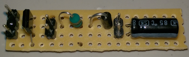
Note: For testing, the solar cell, battery and LED are broken out on 2.54mm Dupont connector pins. For long environmental life you may want to solder the connecting wires before coating the whole unit with a conformal coating / liquid tape etc
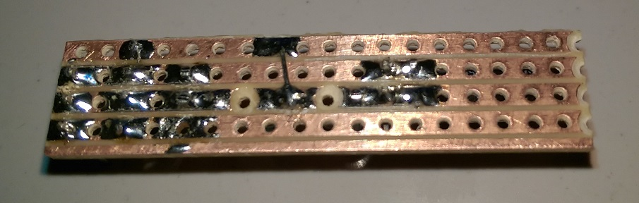
Not the best image - the camera seems to have problems with the shiny copper surface.
I also had a number of PCB's made up by JLC. Very cheap, fast delivery and I like the selection of colours.
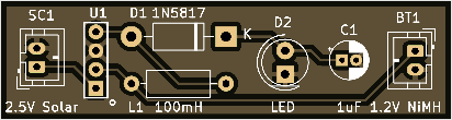
The gebers for both JLC and OSHPARK are included in the project if you want to make your own
| Qty | Value | Footprint | References |
|---|---|---|---|
| 3 | LOGO | 80bus:sleepymouse_very_very_small | G1, G1, G1 |
| 1 | +5V | TestPoint:TestPoint_THTPad_D2.0mm_Drill1.0mm | TP2 |
| 1 | GND | TestPoint:TestPoint_THTPad_D2.0mm_Drill1.0mm | TP1 |
| 1 | Host Z80 | Package_DIP:DIP-40_W15.24mm | J3 |
| 1 | Pin1:20 | Connector_PinHeader_2.54mm:PinHeader_1x20_P2.54mm_Vertical | J1 |
| 1 | Pin21:40 | Connector_PinHeader_2.54mm:PinHeader_1x20_P2.54mm_Vertical | J2 |
| 1 | Z80CPU | 80bus:DIP-40_W15.24mm_ZIF | U1 |
codesqueak/SmallElectronicsProjects
A collection of small projects that can be grouped together

codesqueak/SmallElectronicsProjects
A collection of small projects that can be grouped together

codesqueak/SmallElectronicsProjects
A collection of small projects that can be grouped together

codesqueak/SmallElectronicsProjects
A collection of small projects that can be grouped together

codesqueak/SmallElectronicsProjects
A collection of small projects that can be grouped together

codesqueak/SmallElectronicsProjects
A collection of small projects that can be grouped together

codesqueak/SmallElectronicsProjects
A collection of small projects that can be grouped together


FrameworkComputer/ExpansionCards
Reference designs and documentation to create Expansion Cards for the Framework Laptop

VoronDesign/Voron-Hardware
Cool Hardware designed by the Voron Design group

hackclub/OnBoard
💡 Join 1,000 teenagers and make your first PCB with a $100 grant!


adamws/kicad-kbplacer
KiCad plugin for automatic keyboard's key placement and routing
It measures 58 × 60 mm and has 2 copper layers, 1.6 mm thick.
9 parts. The full list of its parts is on this page, with links to each part's symbol and footprint where PCBKit's library has them.
From the codesqueak/SmallElectronicsProjects repository on GitHub, at the commit this page was made from: the board is Z80Breakout/kicad/Z80Breakout.kicad_pcb and its schematic N1Clock/kicad/N1Clock.kicad_sch. PCBKit opens the board in the browser, with nothing to install.
Its repository states no licence, so its author keeps all rights: ask codesqueak before reusing the design.