2 layers170.2 × 100 mm
Z80-SBC
skiselev/zeta_sbc
Zeta SBC is an Zilog Z80 based single board computer. It is inspired by Ampro Little Board Z80 and N8VEM project. Zeta SBC is software compatible with RomWBW Firmware
75 parts53GPL-3.0

 codesmythe/KEMOJO
PS/2 keyboard, mouse and joystick support for RCBus based on ATmega328
KEMOJO is an open-source printed circuit board by codesmythe, from the codesmythe/KEMOJO repository on GitHub. It is a 4-layer board of 101.6 × 55.9 mm with 28 parts on 119 nets, routed with 552 tracks and 2 vias.
It is built around the ATMEGA328-PU, 74LS04PC and PC16550DV. Its parts include 12 connectors, 5 capacitors, 4 ICs, 1 resistor and 1 diode. It belongs with the keyboards and input boards and the AVR (ATmega, ATtiny) boards of this library.


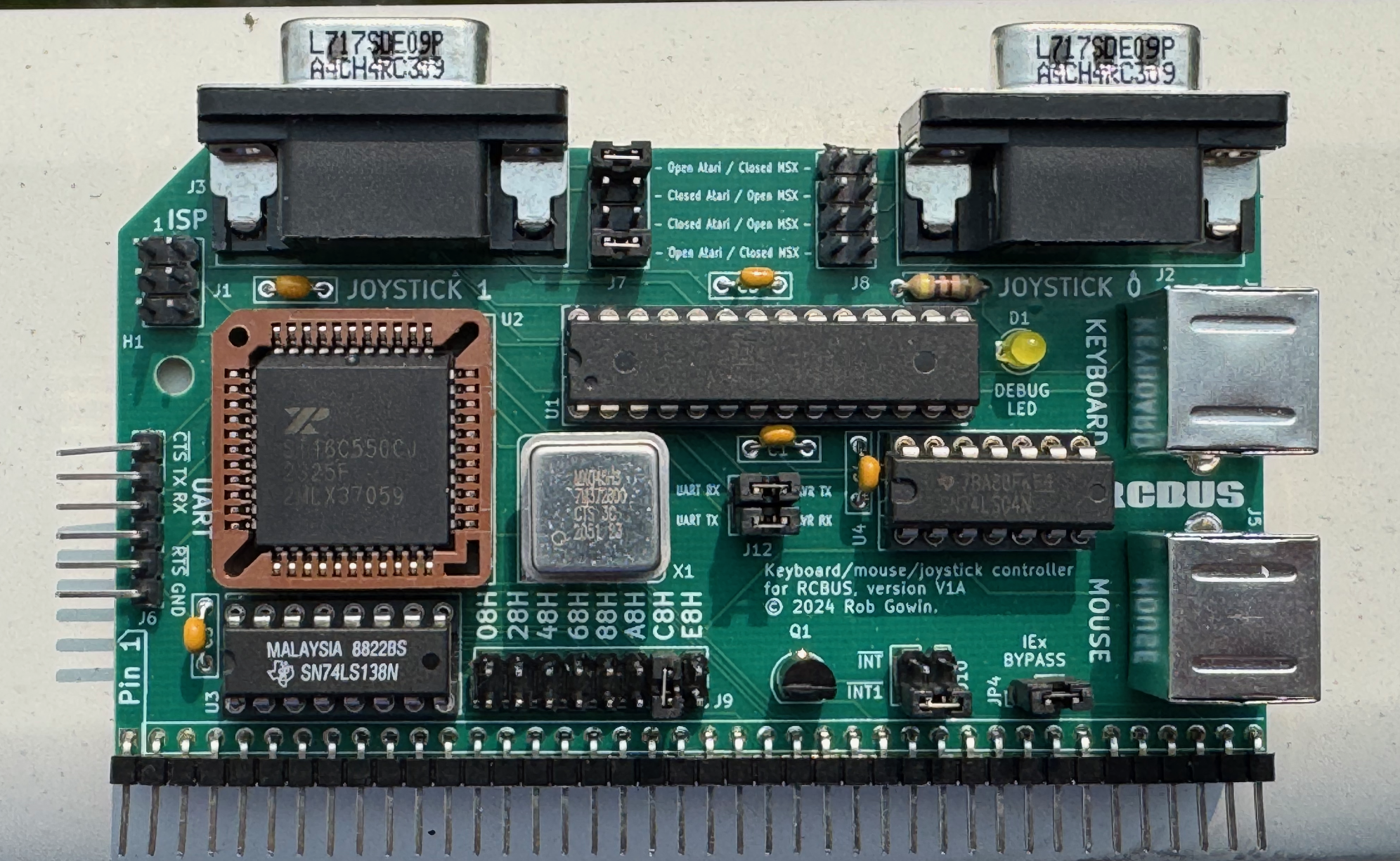
This board provides PS/2 keyboard, PS/2 mouse and Atari or MSX (single button only) joystick support for an RCBus system. It uses the 40-pin RCBus interface.
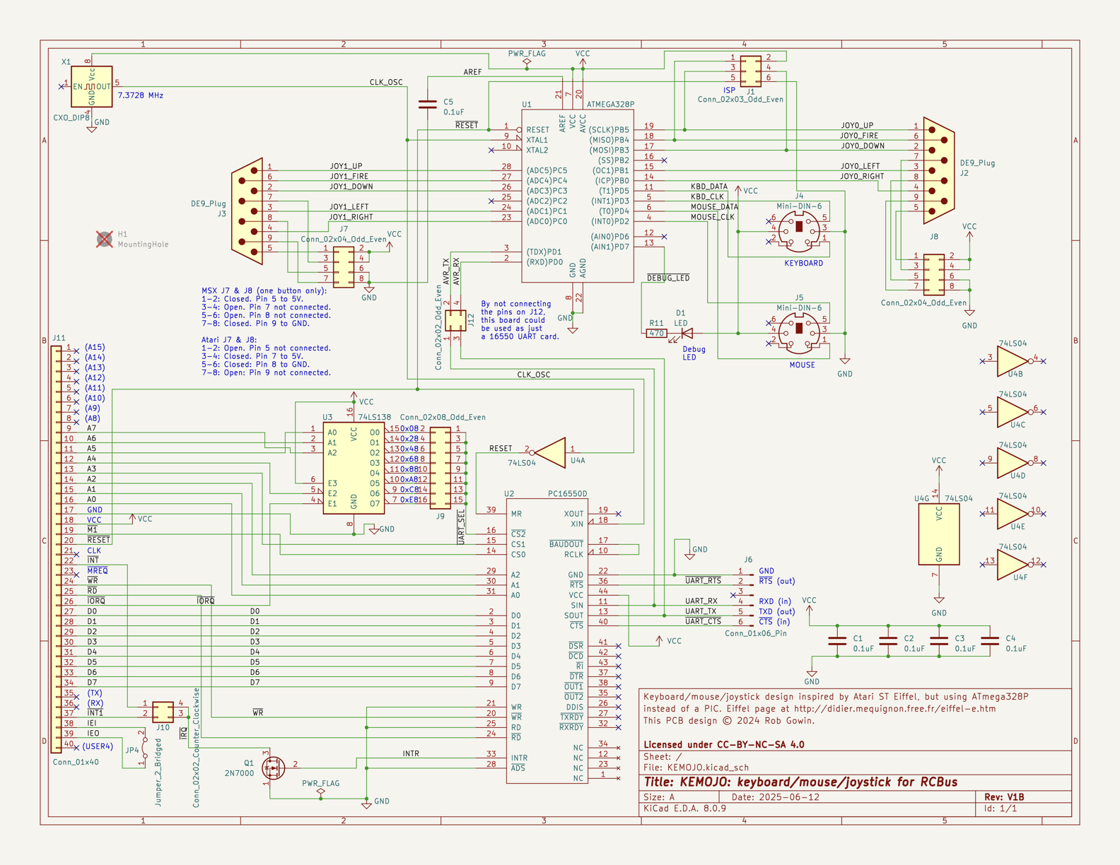
The keyboard, mouse and joystick inputs are read by an ATmega 328P microcontoller. (This is the same MCU that is in the Arduino UNO.) The ATmega implements the Atari ST IKBD protcol and communicates that protocol serially to an RCBus system via a 16C550 UART.
The board was created using Kicad version 8.0.
Click the image to download a PDF version of the schematic.
| Reference | Description |
|---|---|
| J1 | In-system Programming (ISP) port for programming the ATmega328P firmware. |
| J2 | Atari or MSX Joystick 0, Male DE9 D-Sub. See J7 jumper settings below. |
| J3 | Atari or MSX Joystick 1, Male DE9 D-Sub. See J8 jumper settings below. |
| J4 | PS/2 6-pin Mini DIN connector for PS/2 keyboard. |
| J5 | PS/2 6-pin Mini DIN connector for PS/2 mouse. |
| J6 | FTDI Friend connection to 16C550 UART. For debug purposes or UART-only operation. |
| Reference | Description | Comment |
|---|---|---|
| J7, J8 | Atari or MSX operation for Joystick 1/0 | The J7 and J8 jumper blocks configue Joystick 1 and Joystick 0, respectively, for either Atari or MSX joystick operation. In MSX mode, only one fire button is supported. To configure a jumper block for Atari mode, close the top and bottom jumpers, and leave the middle two open. For MSX mode, close the middle two jumpers and leave the top and bottom jumpers open. |
| J9 | I/O Address decode | The J9 jumper block controls where in the Z80 I/O space the KEMOJO board will appear. The TL16C550 UART that communicates with the ATmega328 requires eight I/O addresses, and can be configured to appear at I/O addresses 0x08-0x0F, 0x28-0x2F, 0x48-0x4F, 0x68-0x6F, 0x88-0x8F, 0xA8-0xAF, 0xC8-0xCF or 0xE8-0xEF. |
| J10 | Interrupt connection to RCBus | The board can generate a single interrupt from the TL16C550 UART. Jumper the top two pins of J10 to use the /INT RCBus signal (pin 22) or the bottom two pins to use the RCBus USER1/INT1 signal (pin 37). |
| JP4 | IEx bypass | When the JP4 jumper is closed, the RCBus-Z80 IEI signal (pin 37) is connected directly to the IEO signal (pin 38). When closed, the board is disconnected from RCBus pins 37 and 38. The KEMOJO board does not use IEI or IEO. This jumper is provided to propagate the IEI/IEO daisy chained if required by the system. |
Text file parts list for pasting into the Mouser BOM tool (login required).
Check out the interactive BOM for the board.
To obtain a KEMOJO PCB, download these Gerbers for use at your preferred PCB manufacturer. I use JLCPCB.
| Component Type | Reference | Qty | Description | Part |
|---|---|---|---|---|
| Capacitor | C1,C2,C3,C4,C5 | 5 | 0.1 uF, MLCC, 5 mm Pitch | Mouser 594-K104K15X7RF5WH5 |
| Diode | D1 | 1 | 3 mm, yellow LED indicator | Mouser 859-LTL-4251N |
| Connnector | J1 | 1 | 2x3 straight pin header | Mouser 200-TSW10307TD |
| Connector | J2,J3 | 2 | D-Sub DE9 Male, right angle, PCB mount | Mouser 523-L7SDE9PA4CH4RC39 |
| Connector | J4,J5 | 2 | Circular 6-pin Mini Din Connector for PS/2 | Mouser 490-MD-40SM |
| Connector | J6 | 1 | 1x6 right angle pin header | Mouser 737-PH1RB-06-UA |
| Jumper Block | J7,J8 | 2 | 2x4 straight pin header | Mouser 200-TSW10407TD |
| Jumper Block | J9 | 1 | 2x8 straight pin header | Mouser 200-TSW10807TD |
| Jumper Block | J10 | 1 | 2x2 straight pin header | Mouser 200-TSW10207TD |
| Connector | J11 | 1 | 1x40 right angle pin header | Mouser 710-61304011021 |
| Jumper Block | J12 | 1 | 2x2 straight pin header | Mouser 200-TSW10207TD |
| Jumper | JP4 | 1 | 1x2 straight pin header | Mouser 200-TSW10207TS |
| Transistor | Q1 | 1 | 2N7000 MOSFET in TO92 | Mouser 512-2N7000 |
| Resistor | R11 | 1 | 470 ohm, axial, 1% tolerance, 1/4 W | Mouser 603-MFR-25FTF52-470R |
| Integrated Circuit | U1 | 1 | ATmega328P MCU in 28-pin DIP | Mouser 556-ATMEGA328P-PU |
| Integrated Circuit | U2 | 1 | TL16C550 UART in 44-pin PLCC | Mouser 595-TL16C550CFNR |
| Integrated Circuit | U3 | 1 | 74LS138 in 16-pin DIP | Mouser 595-SN74LS138NE4 |
| Integrated Circuit | U4 | 1 | 74LS04 in 14-pin DIP | Mouser 595-SN74LS04NE4 |
| Oscillator | X1 | 1 | 7.3278 MHz can oscillator in 8-pin DIP | Mouser 774-MXO45HS-3C-7.3 |
| Socket | Socket for U1 | 1 | 28-pin DIP socket | Mouser 737-ICS-328-T |
| Socket | Socket for U2 | 1 | 44-pin PLCC socket | Mouser 575-944424 |
| Socket | Socket for U3 | 1 | 16-pin DIP socket | Mouser 571-1-2199298-4 |
| Socket | Socket for U4 | 1 | 14-pin DIP socket | Mouser 571-1-2199298-3 |
| Socket | Socket for X1 | 1 | 8-pin oscillator socket | Mouser 535-1108800 |
This project has initially inspired by the Atari ST Eiffel 3 project. I've replaced the PIC microcontroller in that project with an easier-to-use ATmega 328P.
The low-level PS/2 code watches the PS/2 keyboard and mouse clock lines for transitions and signals an interrupt the ATmega. This code then reads in PS/2 bytes and buffers them. It was written by Daniel Cliche (@danodus) and is made available by him under an MIT license from here.
The higher level code that implements the Atari ST IKDB protocol is borrowed from the Hatari Atari ST emulator. It is made available under the GNU GPL, version 2 or higher.
The overall project thus uses the GNU GPL, version 2 or higher.
| Qty | Value | Footprint | References |
|---|---|---|---|
| 5 | 0.1uF | Capacitor_THT:C_Rect_L7.0mm_W2.0mm_P5.00mm | C1, C2, C3, C4, C5 |
| 2 | Conn_02x04_Odd_Even | Connector_PinHeader_2.54mm:PinHeader_2x04_P2.54mm_Vertical | J7, J8 |
| 2 | DE9_Plug | Connector_Dsub:DSUB-9_Male_Horizontal_P2.77x2.84mm_EdgePinOffset4.94mm_Housed_MountingHolesOffset7.48mm | J2, J3 |
| 2 | Mini-DIN-6 | CUSTOM:mini_din | J4, J5 |
| 1 | 2N7000 | Package_TO_SOT_THT:TO-92_HandSolder | Q1 |
| 1 | 470 | Resistor_THT:R_Axial_DIN0207_L6.3mm_D2.5mm_P7.62mm_Horizontal | R11 |
| 1 | 74LS04 | Package_DIP:DIP-14_W7.62mm_Socket_LongPads | U4 |
| 1 | 74LS138 | Package_DIP:DIP-16_W7.62mm_Socket_LongPads | U3 |
| 1 | ATMEGA328P | Package_DIP:DIP-28_W7.62mm_Socket_LongPads | U1 |
| 1 | CXO_DIP8 | Oscillator:Oscillator_DIP-8 | X1 |
| 1 | Conn_01x06_Pin | Connector_PinHeader_2.54mm:PinHeader_1x06_P2.54mm_Vertical | J6 |
| 1 | Conn_01x40 | Connector_PinHeader_2.54mm:PinHeader_1x40_P2.54mm_Vertical | J11 |
| 1 | Conn_02x02_Counter_Clockwise | Connector_PinHeader_2.54mm:PinHeader_2x02_P2.54mm_Vertical | J10 |
| 1 | Conn_02x02_Odd_Even | Connector_PinHeader_2.54mm:PinHeader_2x02_P2.54mm_Vertical | J12 |
| 1 | Conn_02x03_Odd_Even | Connector_PinHeader_2.54mm:PinHeader_2x03_P2.54mm_Vertical | J1 |
| 1 | Conn_02x08_Odd_Even | Connector_PinHeader_2.54mm:PinHeader_2x08_P2.54mm_Vertical | J9 |
| 1 | Jumper_2_Bridged | Connector_PinHeader_2.54mm:PinHeader_1x02_P2.54mm_Vertical | JP4 |
| 1 | LED | LED_THT:LED_D3.0mm | D1 |
| 1 | LOGO | RCBUS_LOGO:RCBUS | G*** |
| 1 | MountingHole | MountingHole:MountingHole_3.2mm_M3 | H1 |
| 1 | PC16550D | Package_LCC:PLCC-44_THT-Socket | U2 |
It measures 101.6 × 55.9 mm and has 4 copper layers, 1.6 mm thick.
28 parts, built around the ATMEGA328-PU, 74LS04PC and PC16550DV. The full list of its parts is on this page, with links to each part's symbol and footprint where PCBKit's library has them.
From the codesmythe/KEMOJO repository on GitHub, at the commit this page was made from: the board is hardware/KEMOJO.kicad_pcb and its schematic hardware/KEMOJO.kicad_sch. PCBKit opens the board in the browser, with nothing to install.
Its repository states no licence, so its author keeps all rights: ask codesmythe before reusing the design.
skiselev/zeta_sbc
Zeta SBC is an Zilog Z80 based single board computer. It is inspired by Ampro Little Board Z80 and N8VEM project. Zeta SBC is software compatible with RomWBW Firmware

ja1umi/MUTIF09Project
Various design materials for building my 8-bit-microprocessor-based single board computer(s)

apws/261103-reto-comp-andrew-grok-kicad
Rebuilt Z80 educational schematic in KiCad. The board is not routed yet.


adzierzanowski/z80
Zilog Z80 (and Intel 8080) assembler/disassembler for everyone and some other tools for my private Z80 stuff

aapaetsch/HardwareMonitorArduino
Code, pcb files and schematics for building a hardware monitor based around the atmega328p

