2 layers40 × 20 mm
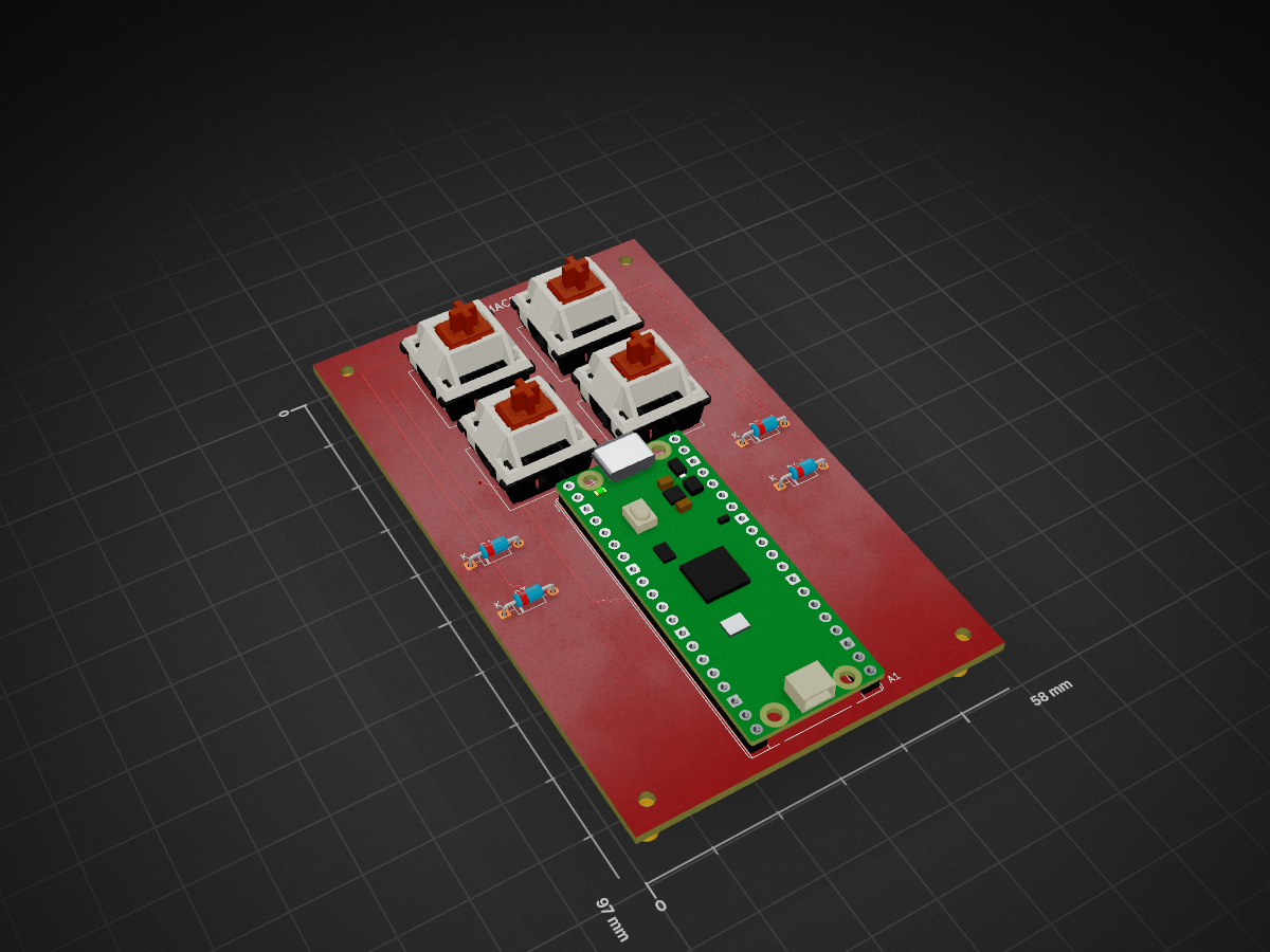
 codejupiter/rp2040-macropad
Open-hardware 2x2 USB mechanical macropad with Raspberry Pi Pico, TinyUSB HID firmware, KiCad PCB sources, and ready-to-order Gerbers.
MacroPad is an open-source printed circuit board by codejupiter, from the codejupiter/rp2040-macropad repository on GitHub. It is a 2-layer board of 58 × 97 mm with 13 parts on 44 nets, routed with 42 tracks and 3 vias.
Its parts include 4 diodes and 4 switches. It belongs with the keyboards and input boards and the RP2040 boards of this library.
This directory contains the editable KiCad 10 source for the 58 x 97 mm, two-layer macropad PCB.
MacroPad.kicad_pro — KiCad project settingsMacroPad.kicad_sch — electrical schematicMacroPad.kicad_pcb — routed PCB and board outlineBOM.csv — machine-readable bill of materialsmanufacturing/macropad_gerbers.zip — manufacturer-ready fabrication archivereports/ — saved electrical-rule and design-rule resultsThe local symbol and footprint tables use KiCad's KICAD10_SYMBOL_DIR and KICAD10_FOOTPRINT_DIR variables, so the project does not depend on a machine-specific application path.
| Net | Pico pin | Function |
|---|---|---|
ROW0 | GP0 / physical pin 1 | Driven low while scanning SW1 and SW2 |
ROW1 | GP1 / physical pin 2 | Driven low while scanning SW3 and SW4 |
COL0 | GP6 / physical pin 9 | Pulled-up input for SW1 and SW3 |
COL1 | GP7 / physical pin 10 | Pulled-up input for SW2 and SW4 |
Every switch connects from a column to a diode anode. Every diode cathode connects to its row. The cathode is the striped end of a physical 1N4148 and is marked K on the silkscreen.
Inspect the Gerber archive with the board house viewer before checkout. The ZIP intentionally contains only fabrication files; editable source remains here in the repository.
| Qty | Value | Footprint | References |
|---|---|---|---|
| 4 | 1N4148 | Diode_THT:D_DO-35_SOD27_P7.62mm_Horizontal | D1, D2, D3, D4 |
| 4 | MountingHole_2.2mm_M2 | MountingHole:MountingHole_2.2mm_M2 | H1, H2, H3, H4 |
| 1 | K00 | Button_Switch_Keyboard:SW_Cherry_MX_1.00u_PCB | SW1 |
| 1 | K01 | Button_Switch_Keyboard:SW_Cherry_MX_1.00u_PCB | SW2 |
| 1 | K10 | Button_Switch_Keyboard:SW_Cherry_MX_1.00u_PCB | SW3 |
| 1 | K11 | Button_Switch_Keyboard:SW_Cherry_MX_1.00u_PCB | SW4 |
| 1 | RaspberryPi_Pico | Module:RaspberryPi_Pico_Common_THT | A1 |
It measures 58 × 97 mm and has 2 copper layers, 1.6 mm thick.
13 parts. The full list of its parts is on this page, with links to each part's symbol and footprint where PCBKit's library has them.
From the codejupiter/rp2040-macropad repository on GitHub, at the commit this page was made from: the board is hardware/MacroPad.kicad_pcb and its schematic hardware/MacroPad.kicad_sch. PCBKit opens the board in the browser, with nothing to install.
Its repository states no licence, so its author keeps all rights: ask codejupiter before reusing the design.


samyk/magspoof
A portable device that can spoof/emulate any magnetic stripe, credit card or hotel card "wirelessly", even on standard magstripe (non-NFC/RFID) readers.

fossasia/pslab-scripts
Pocket Science Lab - Scripts for Sensor Experiments


willem-pennings/balancing-cube
A cube that balances itself in a corner or edge using reaction wheels

VoronDesign/Voron-Hardware
Cool Hardware designed by the Voron Design group

hoglet67/RGBtoHDMI
Bare-metal Raspberry Pi project that provides pixel-perfect sampling of Retro Computer RGB/YUV video and conversion to HDMI