2 layers20.1 × 14.7 mm

 cnvogelg/es_buddy4
EuroShield Buddy PCB Boards
Es base is an open-source printed circuit board by cnvogelg, from the cnvogelg/es_buddy repository on GitHub, published under the CC-BY-SA-4.0 licence. It is a 2-layer board of 20.1 × 128.5 mm with 30 parts on 38 nets, routed with 500 tracks and 5 vias.
Its parts include 16 connectors, 7 resistors and 4 diodes.
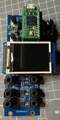
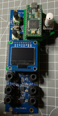
EuroShield Buddy PCB Boards and Arduino Library.
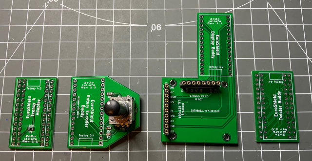
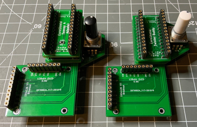
You can combine these boards as you like.
Licensed by Creative Commons Attribution Share Alike 4.0 International
Version: 1.1
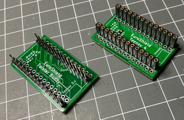
This little adapter board allows to use a Teensy 4.0 board on your EuroShield 1 (short ES) eurorack module.
This is the required re-routing of the Pins:
| Teensy 3.x / EuroShield Pin | Teensy 4.x Pin | Description |
|---|---|---|
| GND | GND | |
| 0 | 0 | Midi IN |
| 1 | 1 | Midi Out |
| 2 | 2 | Button on ES and on Rotary Encoder |
| 3 | 3 | LED 1 |
| 4 | 4 | LED 2 |
| 5 | 5 | LED 2 |
| 6 | 6 | LED 3 |
| 7 | 11 | SPI MOSI |
| 8 | 9 | Display Reset |
| 9 | 21 | Audio BCLK |
| 10 | 10 | SPI CS |
| 11 | 23 | Audio MCLK - A 100 Ohm Resistor is required here! |
| 12 | 12 | SPI MISO |
| Teensy 3.x / EuroShield Pin | Teensy 4.x Pin | Description |
|---|---|---|
| VIN | VIN | |
| AGND | AGND | |
| 3.3V | 3.3V | |
| 23 | 20 | Audio LRCLK |
| 22 | 7 | Audio TX DIN |
| 21 | 15 | Lo Pot on ES |
| 20 | 14 | Hi Pot on ES |
| 19 | 19 | I2C SCL |
| 18 | 18 | I2C SDA |
| 17 | 17 | Rotary Encoder A |
| 16 | 16 | Rotary Encoder B |
| 15 | 22 | Display CMD/Data |
| 14 | 13 | SPI SCK |
| 13 | 8 | Audio RX DOUT |
All Pins are direclty connected expect Audio MCLK is connected via a 100 Ohm resistor.
Version: 1.1
Add a rotary encoder with button to your Euroshield.
| Symbol | Part | Description | Mouser No. |
|---|---|---|---|
| ROT1 | PEC12R-3220F-S0024 | Bourns Rotary Encoder | 652-PEC12R3220FS0024 |
| R1-R3 | SMD 0805 10k | 10k Resistor | 71-CRCW080510K0FKEAC |
Version: 1.1
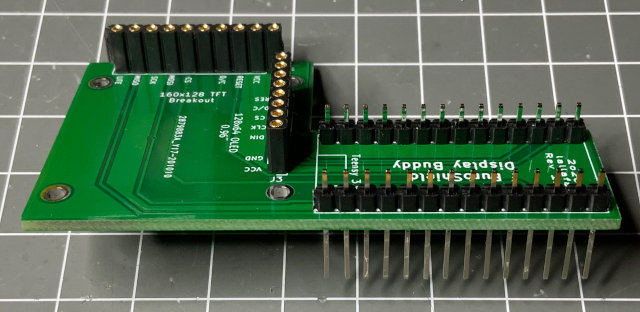
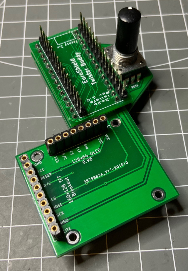
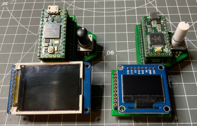
Add an SPI LCD or OLED display to your EuroShield. While the OLED with 128 x 64 fits nicely into the form factor of the shield, the LCD is wider and offers 160 x 128 colored pixels.
The LCD has the following parameters:
| LCD Pin | Teensy 3.2 Pin | Description |
|---|---|---|
| 1 | GND | GND |
| 2 | 3.3V | 3.3V |
| 3 | 8 | Display Reset |
| 4 | 15 | Display Cmd/Data |
| 5 | - | N/A |
| 6 | 10 | SPI CS |
| 7 | 7 | SPI MOSI |
| 8 | 14 | SPI SCK |
| 9 | 12 | SPI MISO |
| 10 | 3.3V | Display Light |
I use an Adafruit 1.8" Color TFT LCD display with MicroSD Card Breakout (358)
The OLED has the following parameters:
| OLED Pin | Teensy 3.2 Pin | Description |
|---|---|---|
| 1 | 3.3V | 3.3V |
| 2 | GND | GND |
| 3 | - | N/A |
| 4 | 7 | SPI MOSI |
| 5 | 14 | SPI SCK |
| 6 | 10 | SPI CS |
| 7 | 15 | Display Cmd/Data |
| 8 | 8 | Display Reset |
Version: 1.0
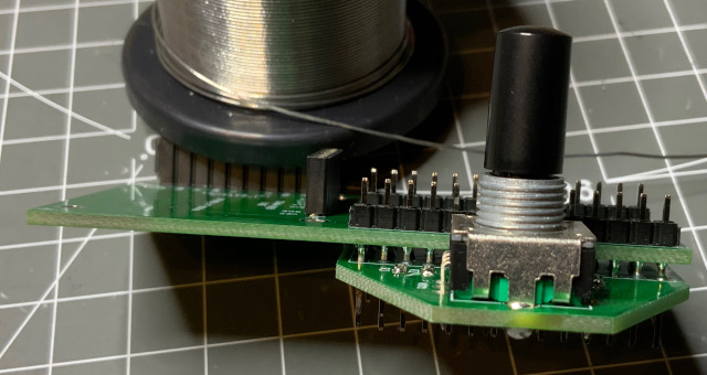
Turn the Teensy around so that the USB connector points upwards and a connected USB cable gets out of the way and does not obstruct the display.
If you want to build the full stack of buddy boards:
| Qty | Value | Footprint | References |
|---|---|---|---|
| 4 | 1k | Resistor_SMD:R_0805_2012Metric_Pad1.15x1.40mm_HandSolder | R4, R5, R6, R7 |
| 4 | AudioJack2_SwitchT | Connector_Audio:Jack_3.5mm_QingPu_WQP-PJ398SM_Vertical_CircularHoles | J9, J10, J11, J12 |
| 4 | LED | LED_THT:LED_D3.0mm | D1, D2, D3, D4 |
| 3 | 1K | Resistor_SMD:R_0805_2012Metric_Pad1.15x1.40mm_HandSolder | R1, R2, R3 |
| 2 | MountingHole | MountingHole:MountingHole_3.2mm_M3_ISO14580_Pad | H1, H2 |
| 1 | ENC | Connector_PinHeader_2.54mm:PinHeader_1x06_P2.54mm_Vertical | J1 |
| 1 | EXT_I2C | Connector_PinHeader_2.54mm:PinHeader_2x03_P2.54mm_Vertical | J8 |
| 1 | I2C | Connector_PinHeader_2.54mm:PinHeader_1x06_P2.54mm_Vertical | J3 |
| 1 | MODA | Connector_PinHeader_2.54mm:PinHeader_2x03_P2.54mm_Vertical | J13 |
| 1 | MODB | Connector_PinHeader_2.54mm:PinHeader_2x03_P2.54mm_Vertical | J14 |
| 1 | MODC | Connector_PinHeader_2.54mm:PinHeader_2x03_P2.54mm_Vertical | J15 |
| 1 | MODD | Connector_PinHeader_2.54mm:PinHeader_2x03_P2.54mm_Vertical | J16 |
| 1 | ROTARY-ENCODER | cvparts:Rotary_Encoder_PEC12R-3220F-S0024 | ROT1 |
| 1 | SPI | Connector_PinHeader_2.54mm:PinHeader_1x06_P2.54mm_Vertical | J2 |
| 1 | TFT | Connector_PinHeader_2.54mm:PinHeader_1x10_P2.54mm_Vertical | J5 |
| 1 | USB_CON | Connector_PinHeader_2.54mm:PinHeader_1x05_P2.54mm_Vertical | J6 |
| 1 | USB_PAD | Connector_PinHeader_2.54mm:PinHeader_1x02_P2.54mm_Vertical | J7 |
| 1 | XTRA | Connector_PinHeader_2.54mm:PinHeader_1x06_P2.54mm_Vertical | J4 |


google/mozc-devices
Circuit diagrams and firmware source code for Gboard DIY keyboards


VoronDesign/Voron-Hardware
Cool Hardware designed by the Voron Design group

hoglet67/RGBtoHDMI
Bare-metal Raspberry Pi project that provides pixel-perfect sampling of Retro Computer RGB/YUV video and conversion to HDMI

tenderlove/initial-v
It's a BMW shifter converted to a Bluetooth Keyboard that you use with Vim

hackclub/OnBoard
💡 Join 1,000 teenagers and make your first PCB with a $100 grant!


It measures 20.1 × 128.5 mm and has 2 copper layers, 1.6 mm thick.
30 parts. The full list of its parts is on this page, with links to each part's symbol and footprint where PCBKit's library has them.
From the cnvogelg/es_buddy repository on GitHub, at the commit this page was made from: the board is hardware/es_base/es_base.kicad_pcb. PCBKit opens the board in the browser, with nothing to install.
Its repository publishes it under the CC-BY-SA-4.0 licence: you may reuse it on that licence's terms (keep the author's notice, and for a copyleft licence share your changes alike).