2 layers30 × 56 mm
 cmarrin/PostLightController
Code for Pond controller
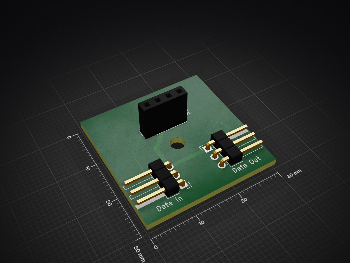
Passive is an open-source printed circuit board by cmarrin, from the cmarrin/PostLightController repository on GitHub, published under the MIT licence. It is a 2-layer board of 30 × 30 mm with 4 parts on 4 nets, routed with 23 tracks and 0 vias.
This is a controller for post lights along my fence. Each post has a NeoPixels 8 pixel ring and an Arduino Nano to drive it. It receives serial data from a Raspberry Pi with 0-5v levels and no line conditioning other than 0.01uf capacitors on the input and output serial lines. Data comes in on pin 11 and is sent out on pin 10. Post Light Controllers are connected in serial. The previous controller sends data to the next. Each serial packet contains an address. An address of 0 sends the packet to all controller, so every byte is simply passed on. If the address is 1, this packet is for the receiving controller. It consumes it and doesn't send it on. If it is greater than 1 the address is decremented and the packet is sent to the next controller. So for instance an address of 5 is consumed by the 5th controller in the chain.
SoftSerial is used to receive and send packets. Each packet consists of a variable number of bytes, starting with a lead-in ('('), address, command and size. This is followed by bytes of payload then by a checksum byte and a lead-out (')'). The command tells the controller what sequence to run. For instance it can set a constant color ('c') of flicker the lights to looks like a burning candle ('f'). The payload is specific to the command. But most commands start with a color as a byte each of hue, saturation and value (brightness).
In order to avoid having to reprogram each post light controller whenever a command is added or changed, the system has an interpreter for a custom language, Clover. See https://github.com/cmarrin/Clover. Clover uses the concepts of commands for calling functions to perform the various lighting effects. Because of the serial interface, commands for the post lights are a single character. You write a function for init and loop (in Arduino terms), indicate how many params are to be passed and associate it with a single character command string. The params passed to the serial interface must match the number of params specified in the command. The Interpreter init() function is called, passing the command and params. Those params are also available to the loop() function. The loop() function returns an int which is the number of milliseconds to delay before calling loop again. This allows accurate timing for the lighting effects.
Clover has a mechanism for adding modules, custom native functions for specific functionality. The post lights use a circular NeoPixel array with 8 addressable RGB LEDs (https://www.ebay.com/itm/392044823820). So the PostLightController adds a NativeColor module. This adds the concept of 4 color "registers" which can be manipulated by the functions in the module. There are functions to load a color (3 byte HSV) from the Params into one of the registers, loading and storing one color component (HSV) in one of the registers, and setting one light or all lights from a color register.
Commands are uploaded to the Aduino from the serial port in 64 byte binary chunks. The chunks are actually 66 bytes: 64 data bytes preceeded by a 2 byte offset of where to put the bytes in EEPROM. The Clover source is compiled on Mac into a series of 64 byte chunks saved to disk. A Node Red project (https://github.com/cmarrin/PondController-node-red-mac and https://github.com/cmarrin/PondController-node-red-mac) is used to upload. The Mac version is for testing but the system is intended to be run on a Raspberry Pi connected through its hardware serial port. You can connect to a PostLightController board from a USB to Serial board connected to the Mac and use the Node Red project to upload using the Send Executable button. See below for how to set up Node Red on Mac and RPi. The Mac compiler is a command line tool. You give it the Clover source file with the '-s' option to output a sequence of files with the same name as the input file minus the '.clvr' suffix, with a 2 digit sequence number and '.arlx'. These file are each 66 bytes long except for the last one, which is as long as needed.
To install the Node-Red PostLightController project on Mac, follow these steps:
The Node-Red Serial Out node is set to /dev/tty.usbserial-AD02CUJ5 for use with my USB to Serial board, which is similar to this one: https://www.ebay.com/itm/223507758747. Yours may be different. You can 'ls /dev/tty.usbserial-*' to see the name on your machine. If you have more than one board connected disconnect the others so you can positively identify the board you're using. Note that if you're connected directly connected to your Arduino to program it, that serial port will show up. Unplug it temporarily so you can find the one for your serial board.
Connect to the PostLightController board from your USB to Serial board by connecting Vcc and Gnd to the corresponding pins on the PostLightController input connector (pins 1 and 2), and the serial board's TXD output to the PostLightController input (pin 3). Then copy all the .arlx files to ~/ and hit the Send Executable button. Of course make sure you build and install PostLightController.ino to the Arduino first.
To send PostLightController board to seeedstudio (https://www.seeedstudio.com/fusion_pcb.html):
1) open PostLightController.kicad_pcb

2) go to File->Plot...

3) Make sure Use Extended X2 Format is not checked

4) Make sure Output folder is 'gbr/'

5) Press Plot to generate all the files

6) Press Generate Drill Files...

7) Press Generate Drill Files on the sheet that comes up

8) Go to console in the PostLightController directory and run 'zip PostLightController-gbr.zip gbr/*'

9) Upload the resulting PostLightController-gbr.zip to SeeedStudio| Qty | Value | Footprint | References |
|---|---|---|---|
| 1 | Data In | Connector_PinHeader_2.54mm:PinHeader_1x03_P2.54mm_Horizontal | J1 |
| 1 | Data Out | Connector_PinHeader_2.54mm:PinHeader_1x03_P2.54mm_Horizontal | J2 |
| 1 | NeoPixel | Connector_PinSocket_2.54mm:PinSocket_1x04_P2.54mm_Vertical | J3 |
The 3 most common of 4 parts.
It measures 30 × 30 mm and has 2 copper layers, 1.6 mm thick.
4 parts. The full list of its parts is on this page, with links to each part's symbol and footprint where PCBKit's library has them.
From the cmarrin/PostLightController repository on GitHub, at the commit this page was made from: the board is kicad/Passive/Passive.kicad_pcb and its schematic kicad/Passive/Passive.kicad_sch. PCBKit opens the board in the browser, with nothing to install.
Its repository publishes it under the MIT licence: you may reuse it on that licence's terms (keep the author's notice, and for a copyleft licence share your changes alike).

joypad-ai/joypad-os
Universal controller firmware for building adapters, dongles, and custom controllers.


hackclub/OnBoard
💡 Join 1,000 teenagers and make your first PCB with a $100 grant!

tardate/LittleArduinoProjects
a collection of "Little Electronic & Arduino Projects", most involving electronics or an Arduino in one way or another!

drandyhaas/KiCadRoutingTools
A set of Python/Rust tools to aid routing in KiCad

osy/XG_Mobile_Station
Open source eGPU dock for ROG Ally and ROG Flow

Luos-io/luos_engine
Open-source and real-time orchestrator for cyber-physical-systems, to easily design, test and deploy embedded applications and digital twins.

NVNTLabs/switch2-SDEX2M2
Micro SD Express to M.2 NVME Adapter for Nintendo Switch 2