
4 layers91.7 × 66.8 mm
Pico expansion board
eamars/RaspberryPi-Pico-Motor-Expansion-Board
A raspberry pi pico expansion board designed for OpenTrickler project
57 parts18GPL-3.0

text BUS+ / GND |-- 7 x XT30 原始总线电源分配 | -- TPS5450DDA --> +5V --> AMS1117-3.3 --> +3.3V | | | -- ESP32、CH340K、逻辑电路 -- 5V 外设接口
ESP32 is an open-source printed circuit board by Cloud-Lightning, from the Cloud-Lightning/ESP32_Distribution_board repository on GitHub. It is a 2-layer board of 49 × 40 mm with 61 parts on 61 nets, routed with 296 tracks and 72 vias.
It is built around the ESP32-WROOM-32UE-N4, CH340K and TPS5450DDA, with the AMS1117-3.3, SS8050 and BZV55B16 among its other parts. Its parts include 20 connectors, 12 capacitors, 12 resistors, 4 ICs and 4 diodes. It belongs with the ESP32 boards of this library.


一块基于 ESP32-WROOM-32UE 的控制与电源分配板,面向机器人、小车或其他多外设嵌入式系统。板卡将原始 BUS+ 电源分配到多组接口,同时生成板载 +5V 和 +3.3V,并提供 USB 下载、UART、显示屏、PWM 和 CAN 总线布线接口。
当前仓库仅包含 KiCad 工程、自定义符号/封装和项目展示图片,不包含装配体、3D 模型源文件及 Gerber/钻孔等生产输出。
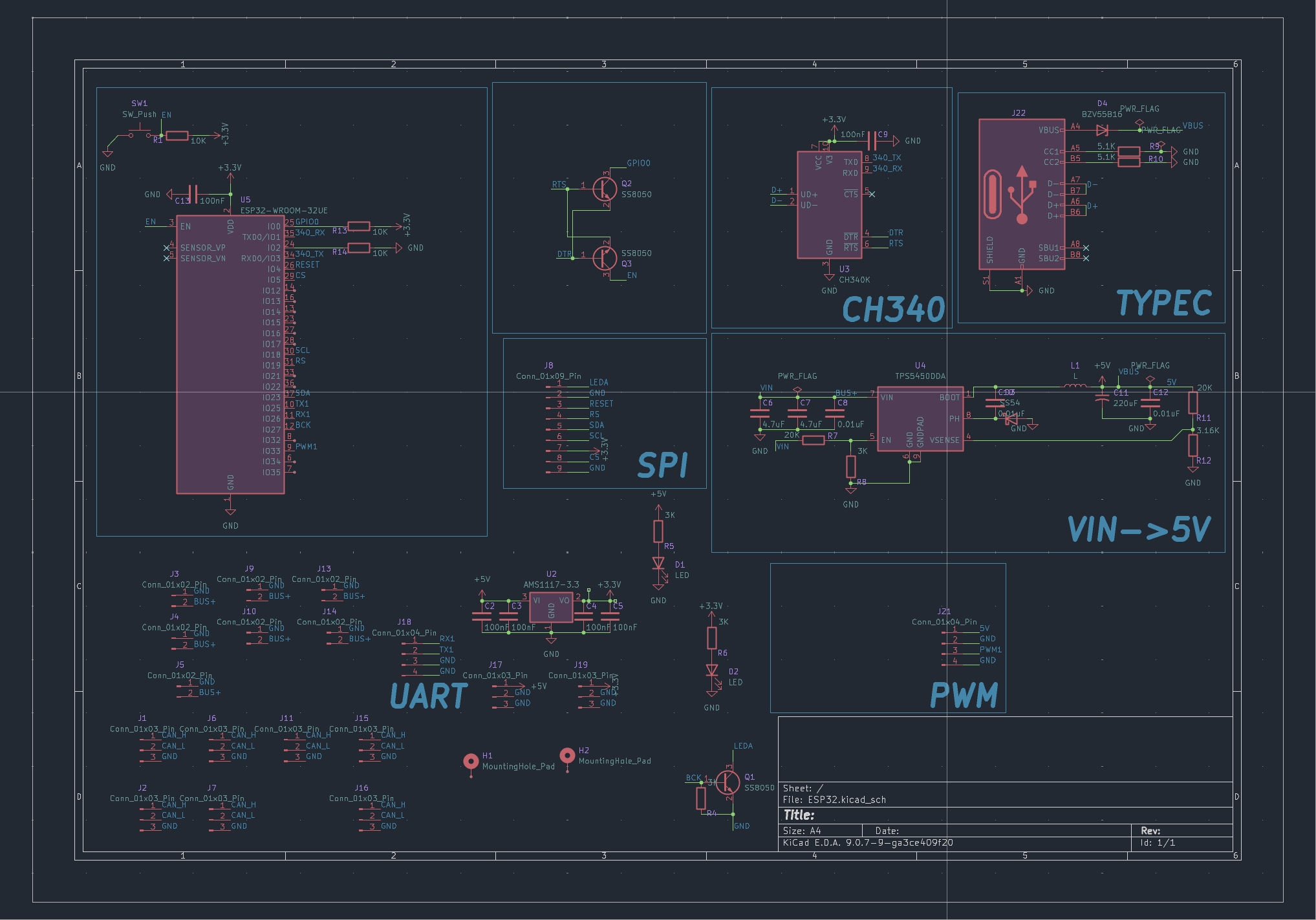
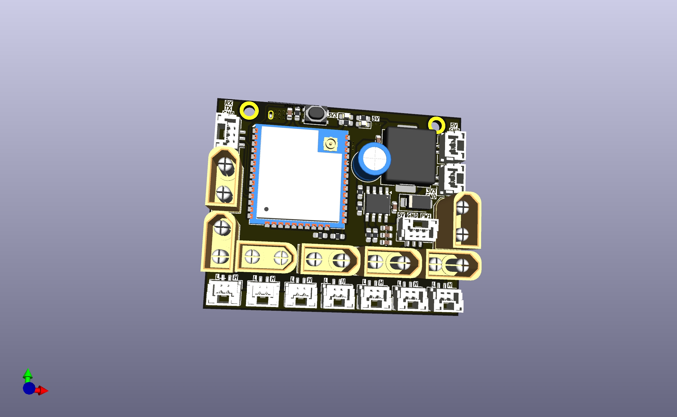
BUS+ 经 TPS5450DDA 降压,原理图标称输出 +5V;AMS1117-3.3 再生成 +3.3V。BUS+ / GND,用于输入或向外设分配未经降压的总线电源。GPIO0 和 EN,支持自动进入下载模式和自动复位。EN 拉低,实现硬件复位。BUS+ / GND
|-- 7 x XT30 原始总线电源分配
|
`-- TPS5450DDA --> +5V --> AMS1117-3.3 --> +3.3V
| |
| `-- ESP32、CH340K、逻辑电路
`-- 5V 外设接口
USB Type-C VBUS -- D4 -- +5VBUS+ 是未经降压的原始电源,不是 5V。所有 XT30 的 BUS+ 端在板上直接相连。
| 接口 | 引脚/网络 | 用途 |
|---|---|---|
| J22 | USB-C VBUS、D+、D-、GND | 供电、固件下载和串口调试 |
| J3/J4/J5/J9/J10/J13/J14 | GND、BUS+ | 原始总线电源输入/并联分配 |
| J1/J2/J6/J7/J11/J15/J16 | CAN_H、CAN_L、GND | CAN 总线被动分配 |
| J18 | RX1、TX1、GND、GND | ESP32 UART1 |
| J21 | +5V、GND、PWM1、GND | PWM 控制外设 |
| J17 | +5V、GND、GND | 5V 辅助供电 |
| J19 | +3.3V、GND、GND | 3.3V 辅助供电 |
| J8 | LEDA、GND、RESET、RS、SDA、SCL、+3.3V、CS、GND | 显示屏/串行外设接口 |
| 板上信号 | ESP32 GPIO | 说明 |
|---|---|---|
| PWM1 | GPIO33 | PWM 输出 |
| TX1 | GPIO25 | UART1 TX |
| RX1 | GPIO26 | UART1 RX |
| BCK | GPIO27 | 通过 Q1 控制显示屏背光 LEDA |
| RESET | GPIO4 | 显示屏/外设复位 |
| CS | GPIO5 | 片选 |
| SCL | GPIO18 | 串行时钟 |
| RS | GPIO19 | 命令/数据选择 |
| SDA | GPIO23 | 串行数据 |
| GPIO0 | GPIO0 | 下载模式控制 |
| 340_TX / 340_RX | GPIO3 / GPIO1 | CH340K 与 ESP32 UART0 |
板上的多组 CAN_H / CAN_L / GND 接口连接到同一组网络,作用是方便总线接线和分配。当前原理图中 没有 CAN 收发器,也没有板载 120 ohm 终端电阻,因此这些接口不能直接把 ESP32 GPIO 转换成 CAN 物理层信号。
使用 CAN 时,需要在总线上另接 CAN 收发器节点,并只在总线两端配置终端电阻。
BUS+ 前,确认 D4 的方向、额定值以及整机的防反灌方案。+5V 和 +3.3V,确认正常后再安装 ESP32 和外设。| 路径 | 内容 |
|---|---|
ESP32.kicad_pro | KiCad 工程配置 |
ESP32.kicad_sch | 原理图 |
ESP32.kicad_pcb | PCB 设计 |
kicad_api_libs/ | 项目自定义符号与封装 |
fp-lib-table / sym-lib-table | 项目库映射 |
工程使用 KiCad 9.0 保存。打开 ESP32.kicad_pro 即可查看和编辑完整设计。
| Qty | Value | Footprint | References |
|---|---|---|---|
| 9 | Conn_01x03_Pin | Connector_JST:JST_GH_BM02B-GHS-TBT_1x02-1MP_P1.25mm_Vertical | J1, J2, J6, J7, J11, J15, J16, J17, J19 |
| 7 | Conn_01x02_Pin | Connector_AMASS:AMASS_XT30U-M_1x02_P5.0mm_Vertical | J3, J4, J5, J9, J10, J13, J14 |
| 6 | 100nF | Capacitor_SMD:C_0603_1608Metric | C2, C3, C4, C5, C9, C13 |
| 4 | 3K | Resistor_SMD:R_0603_1608Metric_Pad0.98x0.95mm_HandSolder | R4, R5, R6, R8 |
| 3 | 0.01uF | Capacitor_SMD:C_0603_1608Metric | C8, C10, C12 |
| 3 | 10K | Resistor_SMD:R_0603_1608Metric_Pad0.98x0.95mm_HandSolder | R1, R13, R14 |
| 3 | SS8050 | Package_TO_SOT_SMD:SOT-23 | Q1, Q2, Q3 |
| 2 | 20K | Resistor_SMD:R_0603_1608Metric_Pad0.98x0.95mm_HandSolder | R7, R11 |
| 2 | 4.7uF | Capacitor_SMD:C_0603_1608Metric | C6, C7 |
| 2 | 5.1K | Resistor_SMD:R_0603_1608Metric_Pad0.98x0.95mm_HandSolder | R9, R10 |
| 2 | Conn_01x04_Pin | Connector_JST:JST_GH_BM03B-GHS-TBT_1x03-1MP_P1.25mm_Vertical | J18, J21 |
| 2 | LED | LED_SMD:LED_0603_1608Metric_Pad1.05x0.95mm_HandSolder | D1, D2 |
| 2 | LOGO | LOGO | G***, G*** |
| 2 | MountingHole_Pad | MountingHole:MountingHole_2.2mm_M2_DIN965_Pad_TopOnly | H1, H2 |
| 1 | 220uF | Capacitor_THT:C_Radial_D6.3mm_H7.0mm_P2.50mm | C11 |
| 1 | 3.16K | Resistor_SMD:R_0603_1608Metric_Pad0.98x0.95mm_HandSolder | R12 |
| 1 | AMS1117-3.3 | Package_TO_SOT_SMD:SOT-89-3 | U2 |
| 1 | BZV55B16 | Diode_SMD:D_SOD-323 | D4 |
| 1 | CH340K | Package_SO:SSOP-10-1EP_3.9x4.9mm_P1mm_EP2.1x3.3mm | U3 |
| 1 | Conn_01x09_Pin | Connector_FFC-FPC:TE_0-1734839-8_1x08-1MP_P0.5mm_Horizontal | J8 |
| 1 | ESP32-WROOM-32UE | RF_Module:ESP32-WROOM-32UE | U5 |
| 1 | L | Inductor_SMD:L_Changjiang_FXL1040 | L1 |
| 1 | SS54 | Diode_SMD:D_SMA | D3 |
| 1 | SW_Push | Button_Switch_SMD:SW_SPST_PTS810 | SW1 |
| 1 | TPS5450DDA | Package_SO:TI_SO-PowerPAD-8_ThermalVias | U4 |
| 1 | USB_C_Receptacle_USB2.0_16P | Connector_USB:USB_16P_加长 | J22 |
It measures 49 × 40 mm and has 2 copper layers, 1.6 mm thick.
61 parts, built around the ESP32-WROOM-32UE-N4, CH340K, TPS5450DDA and AMS1117-3.3. The full list of its parts is on this page, with links to each part's symbol and footprint where PCBKit's library has them.
From the Cloud-Lightning/ESP32_Distribution_board repository on GitHub, at the commit this page was made from: the board is ESP32.kicad_pcb and its schematic ESP32.kicad_sch. PCBKit opens the board in the browser, with nothing to install.
Its repository states no licence, so its author keeps all rights: ask Cloud-Lightning before reusing the design.
eamars/RaspberryPi-Pico-Motor-Expansion-Board
A raspberry pi pico expansion board designed for OpenTrickler project

Icey7122/AM32_AI8051U
Using PWMA to output 3 sets of complementary PWM for driving MOSFEET, Using PWMB for capturing external throttle signals, Using ADC to sample voltage and current, for low voltage protection and over current…

mgalleguilloscespedes-png/proyectro-stm32
en mi afán por el diseño 3d y la electrónica decidí crear mi propia versión de una placa controladora para impresora 3d, basándome en el microcontrolador stm32h723zet6 y la pcb de bigtreetech manta mp8

NguyenThanhHuy-debug/PCB-Liquid-Dispensing-Cabinet
PCB-Liquid-Dispensing-Cabinet — a software project built with modern tooling.

byrantech/stepcraft-3-d600-controller
Open-source FluidNC Controller for the Stepcraft-3/D.600 system.

SEAS2025/mmwave-deer-scan
mmWave FMCW radar deer detection for roadside ambulance safety

DLehenbauer/econopet
Mainboard replacement for Commodore PET/CBM series machines

SRA-VJTI/Evo-Borne
This repository focuses on building an open-source morphobot.