
4 layers160 × 65 mm
Capybara rocket
adam-kabbara/RSX-CANSAT-2026
This is a repository design to manage the files made by the Aerial team under the Robotics for Space eXploration design team at the University of Toronto
174 parts4

 cLLeB/usb-c-charge-controller
Smart USB-C charge controller on the ESP32-C3: KiCad board, C++ firmware with Wi-Fi, Bluetooth and OTA updates, Android and Windows apps
Smartsocket is an open-source printed circuit board by cLLeB, from the cLLeB/usb-c-charge-controller repository on GitHub. It is a 2-layer board of 51.2 × 24 mm with 20 parts on 25 nets, routed with 150 tracks and 14 vias.
It is built around the SI4435DDY. Its parts include 10 resistors, 3 capacitors, 2 diodes, 2 transistors and 2 connectors. It belongs with the radio and wireless boards and the ESP32 and RISC-V boards of this library.
A small adapter that sits between a USB-C charger and a phone and stops charging at a battery level you choose, for example 80 %, then starts again at a lower one, for example 40 %. The phone reports its battery level over Wi-Fi, and the adapter does the switching. I designed the circuit and the board, wrote the firmware and the companion apps, and assembled, soldered and tested it in October 2026.
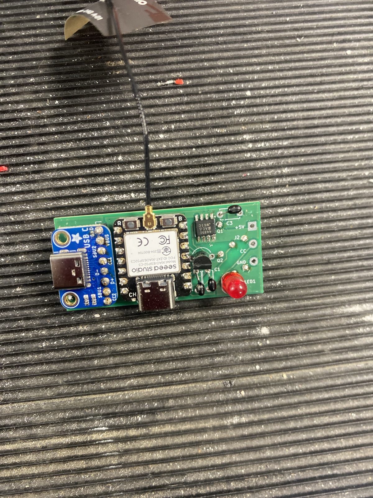
To the charger the adapter looks like a simple 5 V device, and to the phone it looks like a simple 5 V charger. Stopping the charge is the same as pulling the plug out, so every phone already knows how to handle it.
The full circuit table, pin map and decision rules are in DESIGN.md.
C++ for the Seeed XIAO ESP32-C3 in the Arduino environment (firmware/smart_socket/).
smartsocket-xxxxxx.local address, so several can share one network.The decision rules are mirrored in Python in tools/logic.py and covered by 62 scenario tests. tools/test_device.py checks a real adapter feature by feature over Wi-Fi.
Before building, copy firmware/smart_socket/secrets.example.h to secrets.h and set your own update password.
app-android/): finds every adapter on the network, sets one up over Bluetooth, and reports the phone's battery level in the background.app-windows/): every adapter in one list with limits, timer, history and program upload.http://smartsocket.local/api/battery?level=…, described in PHONE-SETUP.md.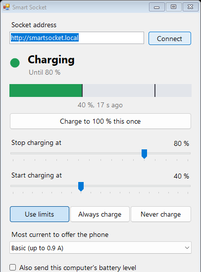
Rev 0.2, 51.2 x 24 mm, two layers, made by PCBWay. The charger plugs into one end and the phone cable leaves from the other. Schematic and board are generated by scripts in kicad/ and checked with ERC, DRC and a netlist comparison.
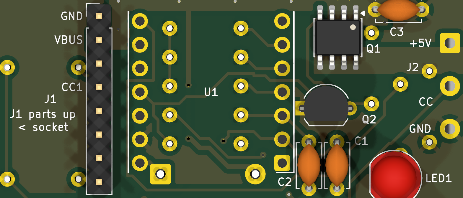 | 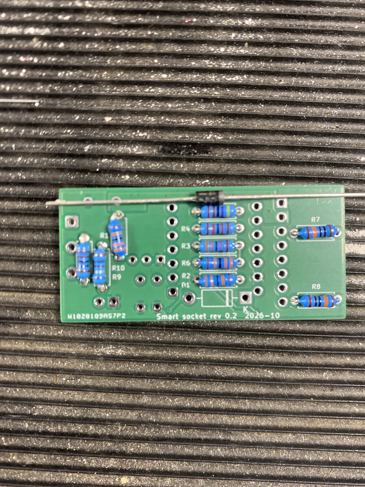 |
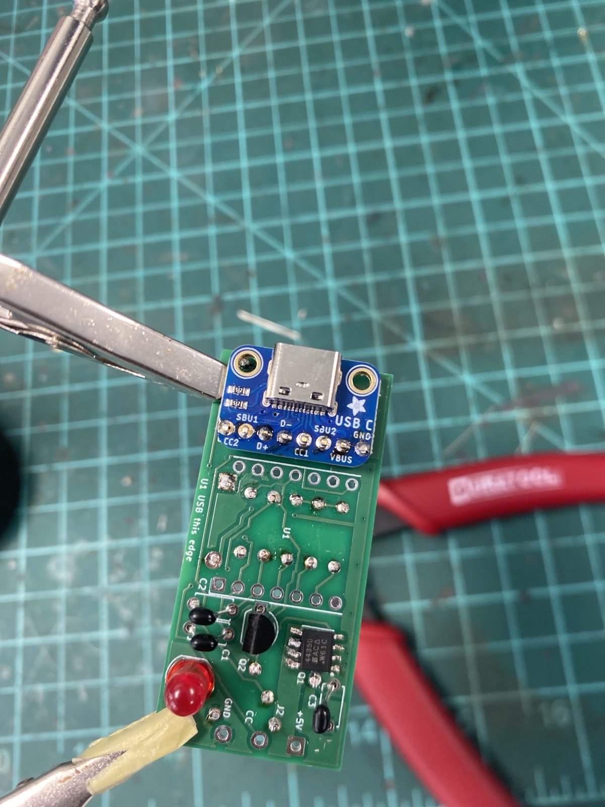 | 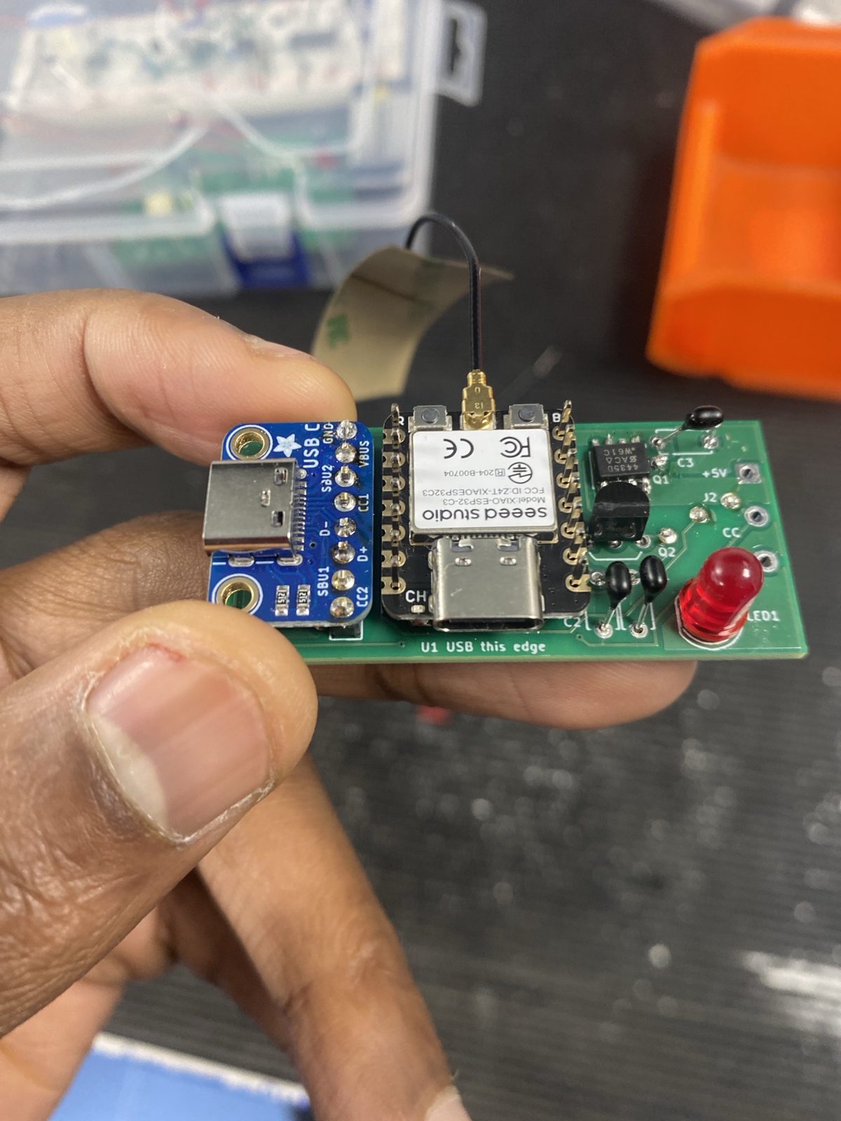 |
A 3D printed case is drafted in OpenSCAD in case/.
ESP32-C3, C++, KiCad, Python, Java for Android, C# for Windows, OpenSCAD.
| Qty | Value | Footprint | References |
|---|---|---|---|
| 3 | 100n | Capacitor_THT:C_Disc_D4.7mm_W2.5mm_P5.00mm | C1, C2, C3 |
| 3 | 330k | Resistor_THT:R_Axial_DIN0207_L6.3mm_D2.5mm_P7.62mm_Horizontal | R1, R2, R6 |
| 2 | 100k | Resistor_THT:R_Axial_DIN0207_L6.3mm_D2.5mm_P7.62mm_Horizontal | R7, R8 |
| 1 | 12k | Resistor_THT:R_Axial_DIN0207_L6.3mm_D2.5mm_P7.62mm_Horizontal | R4 |
| 1 | 1N5817 | Diode_THT:D_DO-41_SOD81_P10.16mm_Horizontal | D1 |
| 1 | 1k | Resistor_THT:R_Axial_DIN0207_L6.3mm_D2.5mm_P7.62mm_Horizontal | R10 |
| 1 | 2N7000 | Package_TO_SOT_THT:TO-92_Inline_Wide | Q2 |
| 1 | 33k | Resistor_THT:R_Axial_DIN0207_L6.3mm_D2.5mm_P7.62mm_Horizontal | R3 |
| 1 | 4.7k | Resistor_THT:R_Axial_DIN0207_L6.3mm_D2.5mm_P7.62mm_Horizontal | R5 |
| 1 | 680 | Resistor_THT:R_Axial_DIN0207_L6.3mm_D2.5mm_P7.62mm_Horizontal | R9 |
| 1 | SI4435DDY | Package_SO:SOIC-8_3.9x4.9mm_P1.27mm | Q1 |
| 1 | USB-C socket board | Connector_PinHeader_2.54mm:PinHeader_1x08_P2.54mm_Vertical | J1 |
| 1 | XIAO ESP32-C3 | Package_DIP:DIP-14_W7.62mm | U1 |
| 1 | cable to phone | Connector_Wire:SolderWire-0.5sqmm_1x03_P4.6mm_D0.9mm_OD2.1mm | J2 |
| 1 | red 5 mm | LED_THT:LED_D5.0mm | LED1 |
It measures 51.2 × 24 mm and has 2 copper layers, 1.6 mm thick.
20 parts, built around the SI4435DDY. The full list of its parts is on this page, with links to each part's symbol and footprint where PCBKit's library has them.
From the cLLeB/usb-c-charge-controller repository on GitHub, at the commit this page was made from: the board is kicad/smartsocket.kicad_pcb and its schematic kicad/smartsocket.kicad_sch. PCBKit opens the board in the browser, with nothing to install.
Its repository states no licence, so its author keeps all rights: ask cLLeB before reusing the design.
adam-kabbara/RSX-CANSAT-2026
This is a repository design to manage the files made by the Aerial team under the Robotics for Space eXploration design team at the University of Toronto


atopile/atopile
Design circuit boards with code! ✨ Get software-like design reuse 🚀, validation, version control and collaboration in hardware; starting with electronics ⚡️

davidphilipbarr/Sweep
Sweep - a small promicro based keyboard inspired by the Ferris.

rusefi/rusefi
rusefi - GPL internal combustion engine control unit

hoglet67/RGBtoHDMI
Bare-metal Raspberry Pi project that provides pixel-perfect sampling of Retro Computer RGB/YUV video and conversion to HDMI