
2 layers56 × 65 mm
SeaTalk1
dotnet/iot
This repo includes .NET Core implementations for various IoT boards, chips, displays and PCBs.
24 parts2.4kMIT

 clin1146/esp-buggy
An autonomous line-following robot built on an STM32F401RE Nucleo board, combining custom C++/Mbed firmware, a bespoke six-sensor infrared PCB, and two parallel PID loops (steering + wheel speed) for fast, stable line…
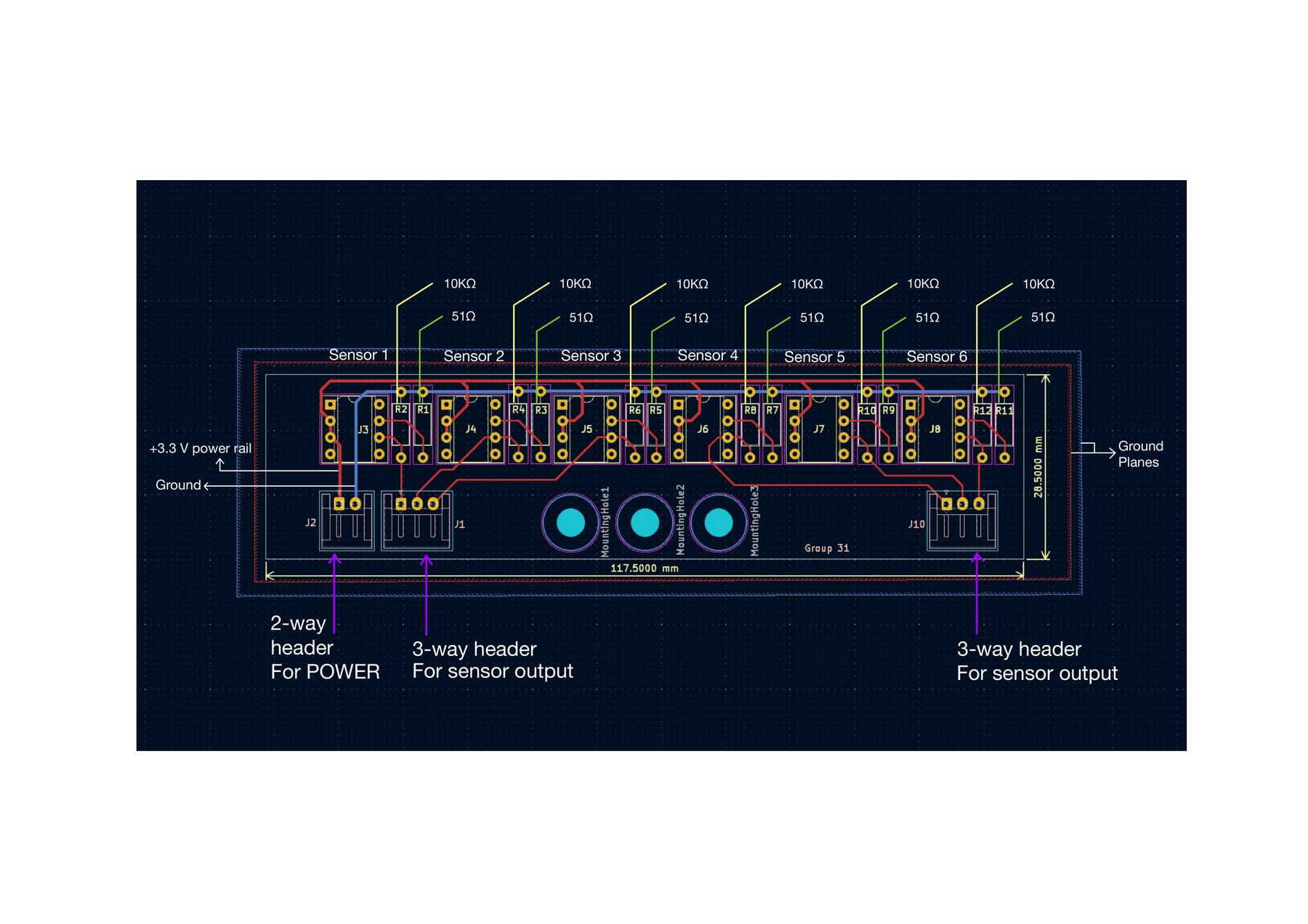
LineSensor is an open-source printed circuit board by clin1146, from the clin1146/esp-buggy repository on GitHub, published under the MIT licence. It is a 2-layer board of 117.5 × 28.5 mm with 24 parts on 38 nets, routed with 111 tracks and 0 vias.
Its parts include 12 resistors and 9 connectors.
An autonomous line-following robot built on an STM32F401RE Nucleo board, combining custom C++/Mbed firmware, a bespoke six-sensor infrared PCB, and two parallel PID loops (steering + wheel speed) for fast, stable line tracking. Built for the EEEN21000 Embedded Systems Project at the University of Manchester and raced in the end-of-year competition.





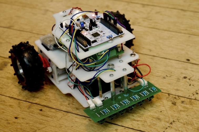
Heats result: completed the competition track in 10.0 s, finishing 6th in the Heats. Technical demonstrations averaged ~90%, with 100% in TD3.
The buggy follows a white line on a dark track using a six-sensor infrared array. Sensor voltages are sampled through the STM32's ADCs, converted to a line position with a weighted-average algorithm, and fed into two PID controllers running in parallel — one for steering, one for wheel speed. Motor commands are issued as bipolar PWM to an H-bridge motor-driver board.
| Property | Value |
|---|---|
| Microcontroller | STM32F401RE (Nucleo-64) |
| Language / framework | C++ / Arm Mbed OS |
| Line sensors | 6 × TCRT5000 reflective IR on a custom PCB, 18 mm pitch |
| Speed feedback | 2 × quadrature encoders, 256 CPR, ×4 decoding |
| Actuation | 2 × brushed DC motors via H-bridge driver, bipolar PWM @ 20 kHz |
| Gearbox | 13.55:1 (16T pinion → 50/10 idler → 60T final drive) |
| Control | Two parallel PID loops (steering error + per-wheel speed) |
| Chassis | 3-tier laser-cut acetal, rear-wheel drive |
| Top speed | ≈ 2.24 m/s flat / ≈ 1.57 m/s on the 18° slope (calculated) |
| Final buggy | SolidWorks model |
|---|---|
| 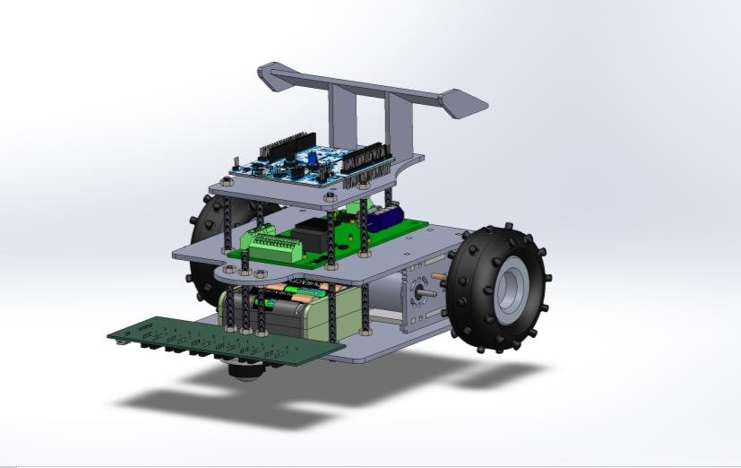 |
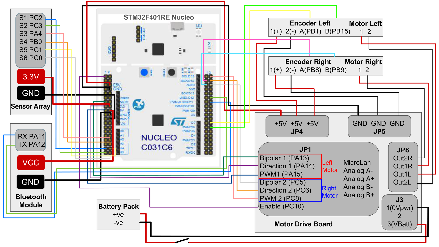
| Custom line-sensor PCB (KiCad) | Wiring |
|---|---|
 |  |
The firmware (firmware/main.cpp) runs the same pipeline every cycle, with
no blocking calls:
SamplingSensor objects sample the TCRT5000 array on a fixed-frequency
Ticker, independently of the main loop.calculate_lineposition() normalises each reading and takes a weighted average —
the weights are the physical sensor offsets — so the result is the buggy's lateral error, with
the setpoint at 0.target − measured RPM from the encoders.baseSpeed + speedCorrection ± steeringAdjustment, sent as
bipolar PWM to the motor-driver board.A three-state machine wraps the pipeline — initial (motors off, variables reset),
run (PID line-following; exits when every sensor reads low, i.e. the all-black end zone),
stop (motors halted). The on-board user button steps between states.
The control system was not originally parallel — see docs/control-system.md for the cascaded → parallel rework, the single change that most improved stability.
esp-buggy/
├── firmware/
│   └── main.cpp                The buggy's control firmware (Mbed / STM32F401RE)
├── docs/
│   ├── hardware.md             Board, pin map, custom PCB, chassis
│   ├── control-system.md       Weighted-average localisation + parallel PID
│   ├── sensor-subsystem.md     Why the TCRT5000 was chosen
│   ├── motor-characterisation.md   Motor constants + gearbox selection
│   └── img/                    Figures
└── hardware/
    ├── wiring-diagram.pdf
    ├── line-sensor-pcb/        KiCad 8 project + PDF / STEP exports
└── chassis/ Laser-cut DXF| Topic | Read |
|---|---|
| Board, full pin map, custom sensor PCB, chassis | docs/hardware.md |
| Control system — weighted-average line position, parallel PID | docs/control-system.md |
| Sensor subsystem — why the TCRT5000 | docs/sensor-subsystem.md |
| Motor characterisation and gearbox selection | docs/motor-characterisation.md |
The steering loop has a hard deadline, derived from the worst case (buggy at top speed):
| Quantity | Value |
|---|---|
| Distance from track centre to the nearest sensor | 0.9 cm |
| Maximum speed | 2.24 m/s |
| ⇒ Steering must react within | 4.02 ms |
| ⇒ Sensor sample period set to | 2 ms (≥ 2 samples per steering decision) |
This is why the firmware is built entirely from tickers and interrupts and avoids blocking calls.
Ki is kept deliberately small. A larger integral term accumulates error over time and
delays corrective action; on a curve that reverses direction sharply, that lag makes the buggy
overshoot and lose the line.printf statements burned MCU cycles and added latency to the
control loop; they should have been compiled out for the race build.Group 31, EEEN21000 Embedded Systems Project, University of Manchester, 2024–25. Tutor: Emad Alsusa.
Charles Lin · Shuocheng Tian · Yefym Lunov · Zain Wilde · Yuncheng Zhang
| Qty | Value | Footprint | References |
|---|---|---|---|
| 6 | 10K | Resistor_THT:R_Axial_DIN0207_L6.3mm_D2.5mm_P10.16mm_Horizontal | R2, R4, R6, R8, R10, R12 |
| 6 | 51 | Resistor_THT:R_Axial_DIN0207_L6.3mm_D2.5mm_P10.16mm_Horizontal | R1, R3, R5, R7, R9, R11 |
| 6 | 8 pin DIL socket | Package_DIP:DIP-8_W7.62mm_Socket | J3, J4, J5, J6, J7, J8 |
| 2 | Conn_01x03_Pin | Connector_JST:JST_EH_S3B-EH_1x03_P2.50mm_Horizontal | J1, J10 |
| 2 | MountingHole_4.3mm_M4 | MountingHole:MountingHole_4.3mm_M4 | mountingHole2, mountingHole3 |
| 1 | Conn_01x02_Pin | Connector_JST:JST_EH_S2B-EH_1x02_P2.50mm_Horizontal | J2 |
| 1 | MountingHole1 | MountingHole:MountingHole_4.3mm_M4 | M3 |
It measures 117.5 × 28.5 mm and has 2 copper layers, 1.6 mm thick.
24 parts. The full list of its parts is on this page, with links to each part's symbol and footprint where PCBKit's library has them.
From the clin1146/esp-buggy repository on GitHub, at the commit this page was made from: the board is hardware/line-sensor-pcb/lineSensor.kicad_pcb and its schematic hardware/line-sensor-pcb/lineSensor.kicad_sch. PCBKit opens the board in the browser, with nothing to install.
Its repository publishes it under the MIT licence: you may reuse it on that licence's terms (keep the author's notice, and for a copyleft licence share your changes alike).
dotnet/iot
This repo includes .NET Core implementations for various IoT boards, chips, displays and PCBs.

pascallanger/DIY-Multiprotocol-TX-Module
Multiprotocol TX Module (or MULTI-Module) is a 2.4GHz transmitter module which controls many different receivers and models.


rusefi/rusefi
rusefi - GPL internal combustion engine control unit

DraftShift/StealthChanger
Tool changing system for Vorons and other front mount printer motion systems, not just stealthburner.

VoronDesign/Voron-Hardware
Cool Hardware designed by the Voron Design group

hackclub/OnBoard
💡 Join 1,000 teenagers and make your first PCB with a $100 grant!
