2 layers54.5 × 81.5 mm
 clarionut/Pulse_Divider_Boolean_Logic1
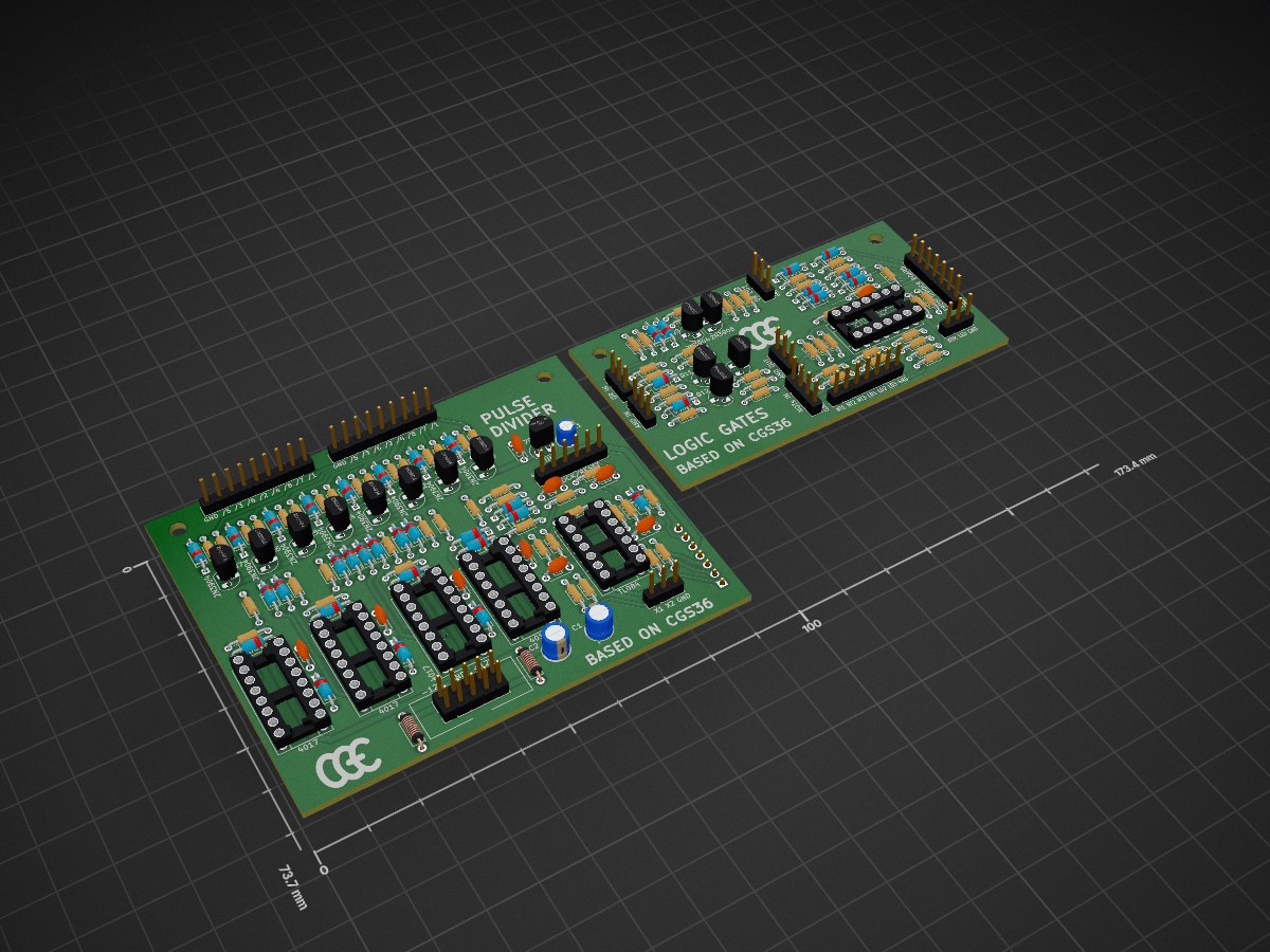
A modifed version of the the CGS36 pulse divider and Boolean logic module with modifications to the low impedance / high current output circuitry and logic gates
CGS36 Pulse Divider is an open-source printed circuit board by clarionut, from the clarionut/Pulse_Divider_Boolean_Logic repository on GitHub. It is a 2-layer board of 173.4 × 73.7 mm with 170 parts on 159 nets, routed with 644 tracks and 5 vias.
It is built around the LM324 and TL084. Its parts include 78 resistors, 37 diodes, 14 connectors, 13 capacitors and 13 transistors.

A synthesizer module based on the original CGS36 circuit.
I was particularly concerned about high current consumption as the original outputs put 15V across a potential divider with a total resistance of 2.8k. Even at Eurorack levels of 12V that's over 4mA per 'on' output, not counting the LEDs. Instead I powered the outputs from a dedicated 78L09 9V supply (I like strong gate/trigger signals) and removed the resistor chain to ground.
The pulse divider now has a /1 output, which is a buffered copy of the incoming clock at the same voltage level as the divided outputs.
There are significant changes to the logic gates too
For reasons of economy I built the pulse divider and Boolean logic circuits on two separate PCBs. The logic board is daisy-chained from the divider board for its power supply, and also uses two stages of the TL084 as its input voltage conditioner. To build this board as a stand-alone unit will require a redesign with power input circuitry and a TL082 as the voltage conditioner.
| Qty | Value | Footprint | References |
|---|---|---|---|
| 37 | 1N914 | CGE_footprints:D_DO-35_SOD27_P7.62mm_Horizontal | D1, D2, D10, D11, D12, D13, D14, D15, D16, D17, D18, D19, D20, D21, D22, D23 +21 |
| 29 | 100k | CGE_footprints:R_Axial_DIN0204_L3.6mm_D1.6mm_P7.62mm_Horizontal | R1, R4, R5, R10, R12, R13, R35, R37, R38, R42, R43, R45, R49, R53, R54, R56 +13 |
| 13 | 200k | CGE_footprints:R_Axial_DIN0204_L3.6mm_D1.6mm_P7.62mm_Horizontal | R14, R15, R16, R17, R18, R19, R20, R36, R47, R55, R64, R73, R76 |
| 11 | 2N3904 | Package_TO_SOT_THT:TO-92_HandSolder | Q0, Q1, Q2, Q3, Q4, Q5, Q6, Q7, Q9, Q11, Q12 |
| 10 | 2k2 | CGE_footprints:R_Axial_DIN0204_L3.6mm_D1.6mm_P7.62mm_Horizontal | R22, R24, R26, R28, R30, R32, R34, R40, R44, R63 |
| 9 | 100n | CGE_footprints:C_Disc_D4.3mm_W1.9mm_P5.00mm | C3, C4, C5, C6, C7, C8, C9, C12, C13 |
| 8 | 33k | CGE_footprints:R_Axial_DIN0204_L3.6mm_D1.6mm_P7.62mm_Horizontal | R21, R23, R25, R27, R29, R31, R33, R77 |
| 5 | 47k | CGE_footprints:R_Axial_DIN0204_L3.6mm_D1.6mm_P7.62mm_Horizontal | R41, R48, R50, R60, R65 |
| 4 | 15k | CGE_footprints:R_Axial_DIN0204_L3.6mm_D1.6mm_P7.62mm_Horizontal | R2, R61, R69, R75 |
| 4 | 1k | CGE_footprints:R_Axial_DIN0204_L3.6mm_D1.6mm_P7.62mm_Horizontal | R46, R58, R67, R72 |
| 4 | 4017 | Package_DIP:DIP-16_W7.62mm_Socket | U2, U3, U4, U5 |
| 3 | 10k | CGE_footprints:R_Axial_DIN0204_L3.6mm_D1.6mm_P7.62mm_Horizontal | R3, R6, R11 |
| 2 | 10u | Capacitor_THT:CP_Radial_D5.0mm_P2.50mm | C1, C2 |
| 2 | 27k | CGE_footprints:R_Axial_DIN0204_L3.6mm_D1.6mm_P7.62mm_Horizontal | R39, R51 |
| 2 | 2N3906 | Package_TO_SOT_THT:TO-92_HandSolder | Q8, Q10 |
| 2 | FB | Inductor_THT:L_Axial_L5.3mm_D2.2mm_P7.62mm_Horizontal_Vishay_IM-1 | FB1, FB2 |
| 2 | LOGO | CGE_footprints:CGE_logo | G***, G*** |
| 1 | 10n | CGE_footprints:C_Disc_D4.3mm_W1.9mm_P5.00mm | C10 |
| 1 | 1u | Capacitor_THT:CP_Radial_D4.0mm_P2.00mm | C11 |
| 1 | AND_IN | Connector_PinHeader_2.54mm:PinHeader_1x03_P2.54mm_Vertical | J13 |
| 1 | AND_OUT | Connector_PinHeader_2.54mm:PinHeader_1x03_P2.54mm_Vertical | J11 |
| 1 | CLK/RST | Connector_PinHeader_2.54mm:PinHeader_1x06_P2.54mm_Vertical | J2 |
| 1 | DivLEDS | Connector_PinHeader_2.54mm:PinHeader_1x09_P2.54mm_Vertical | J5 |
| 1 | DivOUT | Connector_PinHeader_2.54mm:PinHeader_1x09_P2.54mm_Vertical | J6 |
| 1 | FROM_DIVIDER | Connector_PinHeader_2.54mm:PinHeader_1x07_P2.54mm_Vertical | J9 |
| 1 | L78L09_TO92 | Package_TO_SOT_THT:TO-92_HandSolder | U6 |
| 1 | LM324 | Package_DIP:DIP-14_W7.62mm_Socket | U7 |
| 1 | NOT_IN | Connector_PinHeader_2.54mm:PinHeader_1x04_P2.54mm_Vertical | J12 |
| 1 | NOT_OUT | Connector_PinHeader_2.54mm:PinHeader_1x07_P2.54mm_Vertical | J14 |
| 1 | OR_IN | Connector_PinHeader_2.54mm:PinHeader_1x03_P2.54mm_Vertical | J7 |
| 1 | OR_OUT | Connector_PinHeader_2.54mm:PinHeader_1x03_P2.54mm_Vertical | J8 |
| 1 | POWER | CGE_footprints:Power_2x05 | J1 |
| 1 | TL084 | Package_DIP:DIP-14_W7.62mm_Socket | U1 |
| 1 | TO_LOGIC | Connector_PinHeader_2.54mm:PinHeader_1x07_P2.54mm_Vertical | J4 |
| 1 | XOR_IN | Connector_PinHeader_2.54mm:PinHeader_1x03_P2.54mm_Vertical | J3 |
| 1 | XOR_OUT | Connector_PinHeader_2.54mm:PinHeader_1x03_P2.54mm_Vertical | J10 |
The 166 most common of 170 parts.

BojanSof/BluePillWaveGen
DDS function generator build around STM32 BluePill board


m0xpd/EUCLIDplus
EUCLID+ is a Clock Divider, Oscillator and Rhythm Sequencer for electronic music applications


It measures 173.4 × 73.7 mm and has 2 copper layers, 1.6 mm thick.
170 parts, built around the LM324 and TL084. The full list of its parts is on this page, with links to each part's symbol and footprint where PCBKit's library has them.
From the clarionut/Pulse_Divider_Boolean_Logic repository on GitHub, at the commit this page was made from: the board is Schematics/CGS36_Pulse_Divider.kicad_pcb and its schematic Schematics/CGS36_Pulse_Divider.kicad_sch. PCBKit opens the board in the browser, with nothing to install.
Its repository states no licence, so its author keeps all rights: ask clarionut before reusing the design.