
2 layers116.8 × 30 mm
Type d
google/mozc-devices
Circuit diagrams and firmware source code for Gboard DIY keyboards
14 parts3kApache-2.0

 cknave/c64-pico-ram-interface236
Let your Raspberry Pi Pico pretend to be a Commodore 64 ROM cartridge
Picocart is an open-source printed circuit board by cknave, from the cknave/c64-pico-ram-interface repository on GitHub, published under the BSD-3-Clause licence. It is a 2-layer board of 57 × 62 mm with 14 parts on 71 nets, routed with 1,190 tracks and 72 vias.
It is built around the SN74LV244APWRE4. Its parts include 3 capacitors, 3 ICs, 2 resistors, 2 connectors and 1 diode. It belongs with the retro computing and games boards and the RP2040 boards of this library.
This project exposes a 16 KiB window of a Raspberry Pi Pico's RAM to a Commodore 64 via the expansion port. It includes a hardware design and software for the Pico C++ SDK.
 PCB image | 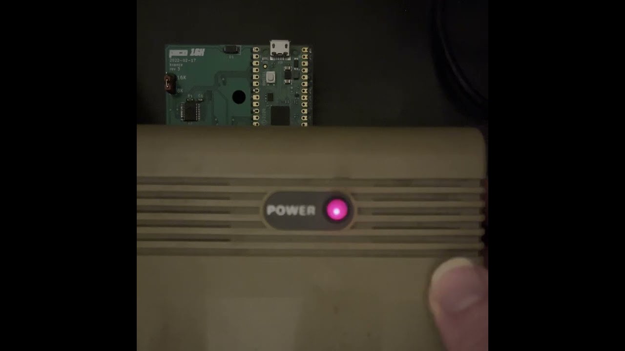 Demo video |
Schematic, PCB, and project files are in KiCad 6 format.
5V power from the expansion port is used to power the Pico. As suggested in the Pico datasheet, a Schottky diode allows the Pico to be connected to powered USB at the same time.
8-bit buffers bring the 5V logic levels on the address and data bus down to 3.3V to protect the Pico's GPIO pins. This means that when the C64 reads from the Pico, it's putting a 3.3V signal on the data bus. At TTL logic levels, this should be fine.
A switch allows you to toggle between an 8K ROM and a 16K ROM by pulling the /GAME line low. This loses half the address space, but lets you boot into BASIC.
The tolerances on the PCB design are compatible with JLCPCB. I ordered my prototypes from them with ENIG surface finish and gold fingers on a 1.6mm thick board. You can get them made much cheaper with HASL, but it will eventually scrape off as you reinsert the board.
Given a 16 KiB-aligned base address on the Pico's address space, four PIO state machines and two DMA channels handle reading addresses from the C64 address bus and writing the requested data to the C64 data bus. The CPU is not needed once this is configured.
To allow the C64 to communicate with the Pico, a 256 byte command area is reserved that will put that byte onto the RX FIFO for the CPU to consume. The CPU can put any value onto the TX FIFO to signal that it is ready for more commands.
Between the GPIO pins and the RAM, there are five logical components:
address_decoder PIO state machine: monitors the /ROML and /ROMH lines for reads, checks if the address is for the special command area, and wakes up either the read or command state machines as needed. Two copies of this state machine run at the same time, monitoring /ROML and /ROMH.
read PIO state machine: reads the address lines, sends the address to DMA, and writes the returned data to the data bus
command PIO state machine: reads the low 8 bits of the address, and copies it to the RX FIFO for the CPU to handle. It writes the STATUS register back to the data bus, indicating if the CPU is busy or not. The CPU can indicate its readiness by writing any value to the TX FIFO.
The special value 00 will not be sent to the CPU at all, allowing the C64 to poll the status
register until the Pico is finished processing a command.
DMA channel 1: write the incoming address to the configuration of DMA channel 2, triggering a read
DMA channel 2: copy a byte at the requested RAM address to the read PIO state machine


It's a Rube Goldberg machine, but the Pico's PIO controllers and DMA can do this in well under the time required by the C64's CPU.
Maybe, but this design is already using all the GPIO pins on the Pico. Even if you replace the "input enable" pin (you can probably get away without it), you'll also need to monitor PHI2. In my experience, the IO lines are glitchy and you need to make sure that you're actually in the right part of the clock cycle to use them.
You could try using a shift register to free up a bunch of pins, but you'll waste a lot of PIO clock cycles shifting all the bits through it. It might be fast enough to only shift a couple of bits.
I think you're definitely in shift register territory at this point, and good luck trying to decode more than a couple of address prefixes in PIO. If you actually do this, please contact me because I want to see it!
Distribute under the terms of the BSD 3-clause license.
The KiCad-RP-Pico footprint is by Nicolò Carandini.
| Qty | Value | Footprint | References |
|---|---|---|---|
| 3 | 0.1μF | Capacitor_SMD:C_0603_1608Metric_Pad1.08x0.95mm_HandSolder | C1, C2, C3 |
| 3 | SN74LV244APWR | picocart:SOP65P640X120-20N | U1, U2, U3 |
| 2 | 10KΩ | Resistor_SMD:R_0603_1608Metric_Pad0.98x0.95mm_HandSolder | R1, R2 |
| 1 | D_Schottky | Diode_SMD:D_SMA | D1 |
| 1 | ExpansionPort | picocart:C64ExpansionEdgeShort | J1 |
| 1 | Pico | picocart:RPi_Pico_SMD_TH | J2 |
| 1 | SW_SPST | Connector_PinHeader_2.54mm:PinHeader_1x03_P2.54mm_Vertical | SW1 |
| 1 | Val** | picocart:logo | Ref** |
The 13 most common of 14 parts.
google/mozc-devices
Circuit diagrams and firmware source code for Gboard DIY keyboards


hackclub/OnBoard
💡 Join 1,000 teenagers and make your first PCB with a $100 grant!


Twotoz/C5VRX
Ultra-minimal, zero-CPU 5.8 GHz analog FPV video receiver using ESP32-C5 Wi-Fi 6 PHY MODEM_DIAG, BitScrambler WBFM demodulation & resistor DAC CVBS


It measures 57 × 62 mm and has 2 copper layers, 1.6 mm thick.
14 parts, built around the SN74LV244APWRE4. The full list of its parts is on this page, with links to each part's symbol and footprint where PCBKit's library has them.
From the cknave/c64-pico-ram-interface repository on GitHub, at the commit this page was made from: the board is pcb/picocart.kicad_pcb and its schematic pcb/picocart.kicad_sch. PCBKit opens the board in the browser, with nothing to install.
Its repository publishes it under the BSD-3-Clause licence: you may reuse it on that licence's terms (keep the author's notice, and for a copyleft licence share your changes alike).