2 layers52 × 20.3 mm
 ciniml/fpga_samples31
FPGA samples
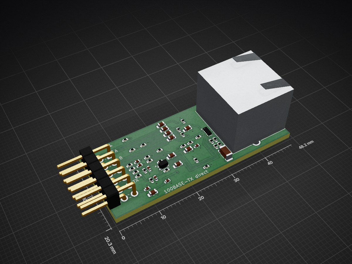
Pmod 100base tx is an open-source printed circuit board by ciniml, from the ciniml/fpga_samples repository on GitHub, published under the BSL-1.0 licence. It is a 2-layer board of 48.2 × 20.3 mm with 48 parts on 27 nets, routed with 208 tracks and 30 vias.
It is built around the TPD4E02B04DQAR, RC0402FR-071ML and RC0402JR-070RL, with the GRM155R61A105KE15D, RC0402FR-0749R9L and C1206C102KGRACTU among its other parts. Its parts include 26 resistors, 17 capacitors, 2 connectors, 1 IC and 1 inductor. It belongs with the fPGA and programmable logic boards of this library.


Raspberry Pi カメラ (15 ピン 1.0 mm FFC, 2 レーン MIPI CSI-2) を Pmod 1 個につなぐ変換基板。
FPGA 側はソフト D-PHY (eda/csi_capture, rtl/csi2)。KiCad 10。
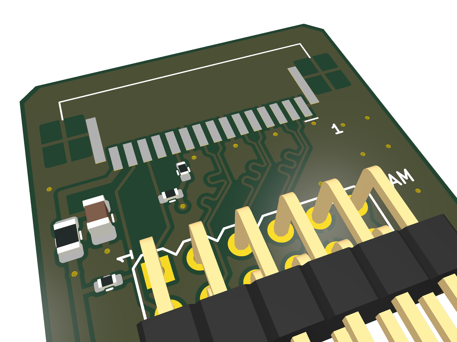
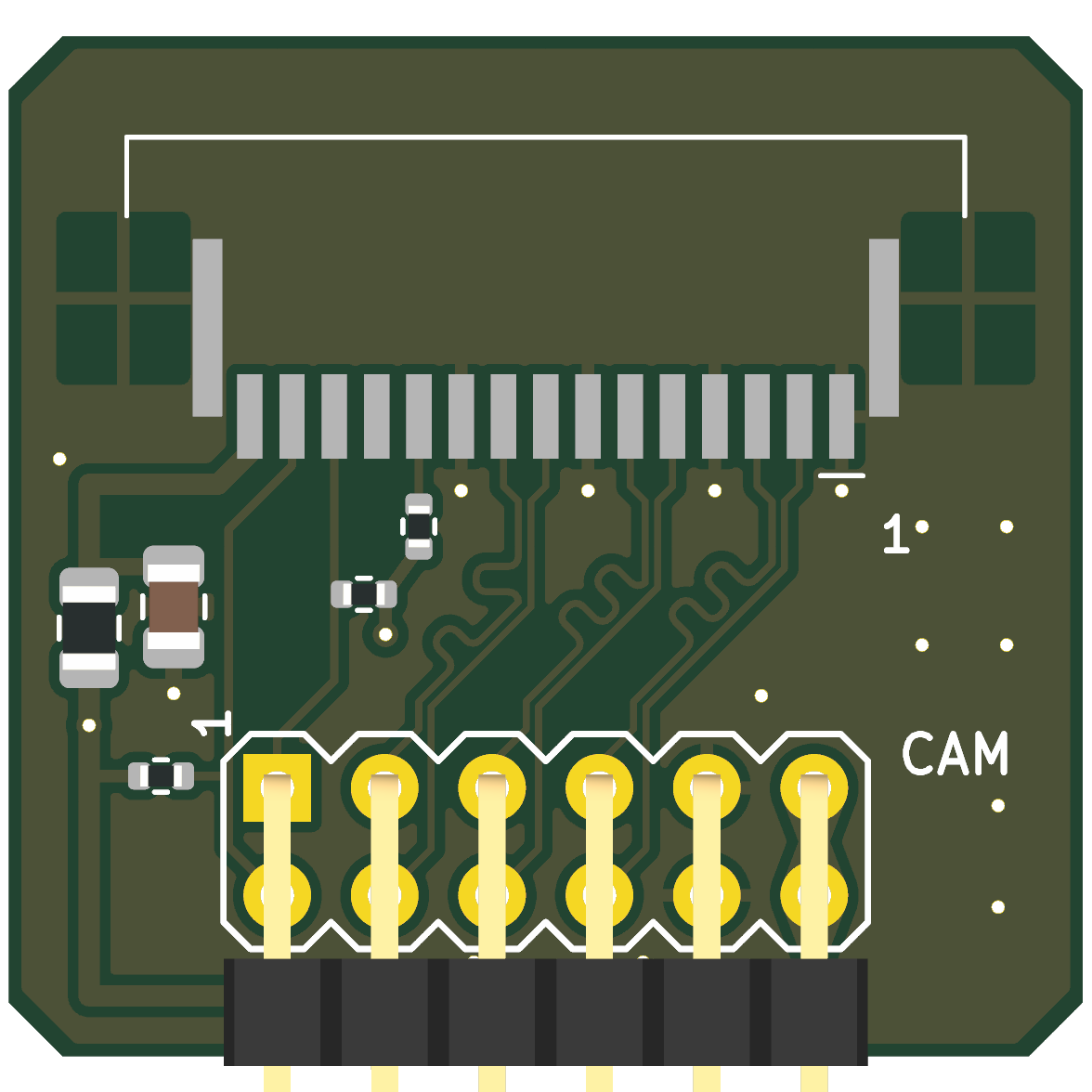
状態: 設計のみ (未発注・実機未確認)。ERC / DRC (回路図との一致を含む) はエラー 0。
Conn_Pmod_Spec_B_Thin)、基板下端Local/local.pretty)。基板上端寄り、ケーブルは上から挿す (ハウジング前端は基板端から 2.5 mm 内側)。
rev A の当初は TE 1-84952-5 だったが JLC 在庫が 1 個のため変更 (接点列の位置は同じ = 配線は無変更)| Pmod | 信号 | FFC | Tang Primer 25K (pmod0) |
|---|---|---|---|
| 1 / 7 | SCL / SDA | 13 / 14 | F5 / G5 |
| 2 / 8 | CLK P / N | 9 / 8 | G7 / G8 |
| 3 / 9 | D1 P / N | 6 / 5 | H8 / H7 |
| 4 / 10 | D0 P / N | 3 / 2 | H5 / J5 |
| 5, 11 | GND | 1, 4, 7, 10, MP | |
| 6, 12 | 3.3 V | 15 (F1 経由) | |
| — | CAM_GPIO | 11 | R3 で 3.3 V へ (カメラは Pmod 給電で即起動) |
| — | CAM_CLK | 12 | 未接続 |
FFC のピン配置は Raspberry Pi 4 公式回路図 (J3 CAMERA) で確認。Pmod 上の並び (CLK, D1, D0) は
FFC 上の並びと同じ順にして、差動対が交差しないようにしてある (FPGA の pins.cst も同じ割り当て)。
FPGA 側の定義は mod/pmod_rpi_camera/pmod_pins.csv。
公式資料から確認済み:
同じコネクタ同士を両端逆面のケーブルでつなぐと、基板の向きによらず ピン n ↔ ピン n になる (3.3V は 15 番どうし、GND は 1 番どうし)。カメラに付属の標準ケーブルを使うこと。 両端が同じ面の社外ケーブルでは逆転し、本基板の 3.3V (15 番) がカメラの GND に当たる (F1 が制限する)。
念のための確認 (カメラをつながずに): ケーブルを J2 に挿し、ケーブル反対端の導体 1 番と Pmod の GND (5/11 番) の 導通をテスタで見る。導通すれば正しい。
tools/build.sh が ERC / DRC (回路図との一致、ベタ再充填込み) を通してから fab/ を作る:
| ファイル | 内容 |
|---|---|
fab/Pmod_RPiCamera_gerber.zip | ガーバー (F/B Cu, Mask, Silk, F.Paste, Edge) + ドリル (PTH/NPTH 別) |
fab/Pmod_RPiCamera_bom.csv | 部品表 (LCSC 番号、MPN 付き) |
fab/Pmod_RPiCamera_pos.csv | 実装位置 (表面のみ、原点は基板左下) |
fab/jlc/Pmod_RPiCamera_jlc_bom.csv, ..._jlc_cpl.csv | JLCPCB 実装用 BOM / CPL (LCSC 番号のある部品のみ。J1 は手はんだ想定で除外) |
fab/lcsc/Pmod_RPiCamera_lcsc_5pcs.csv | LCSC 部品購入用 (5 枚分、J1 含む)。tools/lcsc_order.py N で N 枚分を作り直す (LCSC に問い合わせて最小発注数・単価・在庫を反映、要ネットワーク) |
fab/Pmod_RPiCamera_schematic.pdf | 回路図 |
fab/*.png | 3D レンダリング |
fab/erc.rpt, fab/drc.rpt | 検査結果 (ライブラリ表の警告はヘッドレス環境由来) |
回路図・基板の初版は tools/gen_sch.py / tools/gen_pcb.py で生成し、その後 KiCad で手を入れている
(rev A: P 側の等長化ミアンダ、ティアドロップ、ロゴ、J2 を SFW15R-1STE1LF に変更、LCSC 番号)。KiCad のファイルが正
(スクリプトは初版の TE コネクタのまま)。tools/build.sh は既定で
現状のファイルを検査して出力するだけ。--regen を付けるとスクリプトから作り直し、KiCad での修正は消える。
| Ref | 部品 | LCSC | 備考 |
|---|---|---|---|
| J1 | 2x6 2.54 mm 直角ピンヘッダ | — | 手はんだ想定。JLC で載せるならピン長・本体寸法をフットプリントと照合 (候補 C41417354) |
| J2 | Amphenol SFW15R-1STE1LF | C3168538 | 在庫 9,155、Extended |
| F1 | RUILON SMD0805P050TF (I_hold 0.5 A, 6 V) | C20978 | 代替 Littelfuse 0805L050WR (C207022) |
| C1 | Samsung CL21A106KAYNNNE (10 µF 25 V X5R 0805) | C15850 | Basic |
| R1, R2 | UNI-ROYAL 0402WGF2201TCE (2.2 kΩ) | C25879 | Basic |
| R3 | UNI-ROYAL 0402WGF1002TCE (10 kΩ) | C25744 | Basic |
JLC の配置プレビューで J2 の回転・原点を確認すること (KiCad のフットプリント原点は接点列の中心。 JLC 側のモデル原点と違う場合はオフセットが出る)。J2 の 3D モデルは無い (3D 画像に J2 は写らない)。
../../README.md)| Qty | Value | Footprint | References |
|---|---|---|---|
| 6 | 0.1u/100V | Capacitor_SMD:C_0603_1608Metric | C3, C4, C6, C7, C8, C9 |
| 4 | 1M | Resistor_SMD:R_0402_1005Metric | R23, R24, R25, R26 |
| 4 | 2.2k | Resistor_SMD:R_0402_1005Metric | R9, R10, R11, R12 |
| 4 | 75 | Resistor_SMD:R_0402_1005Metric | R19, R20, R21, R22 |
| 3 | 0.1u | Capacitor_SMD:C_0402_1005Metric | C11, C15, C16 |
| 2 | 0 | Resistor_SMD:R_0402_1005Metric | R5, R6 |
| 2 | 10u | Capacitor_SMD:C_0603_1608Metric | C10, C14 |
| 2 | 120 | Resistor_SMD:R_0402_1005Metric | R3, R4 |
| 2 | 1k | Resistor_SMD:R_0402_1005Metric | R16, R18 |
| 2 | 1u | Capacitor_SMD:C_0402_1005Metric | C12, C13 |
| 2 | 3.3k | Resistor_SMD:R_0402_1005Metric | R15, R17 |
| 2 | 47p | Capacitor_SMD:C_0402_1005Metric | C1, C2 |
| 2 | 49.9 | Resistor_SMD:R_0402_1005Metric | R7, R8 |
| 2 | 62 | Resistor_SMD:R_0402_1005Metric | R1, R2 |
| 1 | 10n/100V | Capacitor_SMD:C_0603_1608Metric | C5 |
| 1 | 180 | Resistor_SMD:R_0402_1005Metric | R14 |
| 1 | 1n/2kV | Capacitor_SMD:C_1206_3216Metric | C17 |
| 1 | 270 | Resistor_SMD:R_0402_1005Metric | R13 |
| 1 | CMC 90R@100MHz | pmod_100base_tx:L_CommonModeChoke_2012Metric_FlowThrough | L1 |
| 1 | Logo_Open_Hardware_Small | pmod_100base_tx:logo | LOGO1 |
| 1 | Pmod 2x6 R/A male | pmod_100base_tx:Pmod_Peripheral_2x06_P2.54mm_Horizontal | J1 |
| 1 | RJ45 8P8C no magnetics | Connector_RJ:RJ45_Amphenol_RJHSE5380 | J2 |
| 1 | TPD4E02B04 | Package_SON:USON-10_2.5x1.0mm_P0.5mm | U1 |


binaryBeachLLC/tradewind
Tradewind TW-1: solar LoRaWAN field sensor. KiCad 9 board, CadQuery enclosure, RUI3 firmware, simulations, test data, report and datasheet.

filliformes/pandore
pandore is an open-source digital audio instrument protyping platform based on the LattePanda Mu.

Andreuxxx1977/esp32-p4
An open-hardware, actively cooled ESP32-P4 board for heavy multimedia work: a 2-lane MIPI camera, a 2-lane MIPI display, USB 2.0 High-Speed, 10/100 Ethernet, UHS-I microSD, 32 MB flash and 32 MB PSRAM.


It measures 48.2 × 20.3 mm and has 2 copper layers, 1.6 mm thick.
48 parts, built around the TPD4E02B04DQAR, RC0402FR-071ML, RC0402JR-070RL and GRM155R61A105KE15D. The full list of its parts is on this page, with links to each part's symbol and footprint where PCBKit's library has them.
From the ciniml/fpga_samples repository on GitHub, at the commit this page was made from: the board is eda/pmod_100base_tx/kicad/pmod_100base_tx.kicad_pcb and its schematic eda/csi_capture/hw/Pmod_RPiCamera/Pmod_RPiCamera.kicad_sch. PCBKit opens the board in the browser, with nothing to install.
Its repository publishes it under the BSL-1.0 licence: you may reuse it on that licence's terms (keep the author's notice, and for a copyleft licence share your changes alike).