Skip to the content
PCBKitNew board
2 layers36.8 × 16.5 mmI2c header x5, the printed circuit board in 3D

NTP synchronized desktop 7-segment clock

Size
36.8 × 16.5 mm
Copper layers
2
Thickness
1.6 mm
Parts
12
Nets
5
Pads
33
Tracks, vias
15, 0
Pours
1
Routed
Yes
KiCad
KiCad 5 (file 20171130)
Created
23 Aug 2021
Updated
25 Jan 2022

Overview

I2c header x5 is an open-source printed circuit board by chudsaviet, from the chudsaviet/ntpclock repository on GitHub. It is a 2-layer board of 36.8 × 16.5 mm with 12 parts on 5 nets, routed with 15 tracks and 0 vias.

It belongs with the lEDs and displays boards of this library.

README

README.md

NTP synchronized desktop 7-segment clock

Features

  1. NTP sunchronization using WiFi.
  2. RTC backup - will show time from a high precision RTC if WiFi is not available.
  3. Automatic display brightness control.
  4. Automatic timezone data update from online TZDATA database.
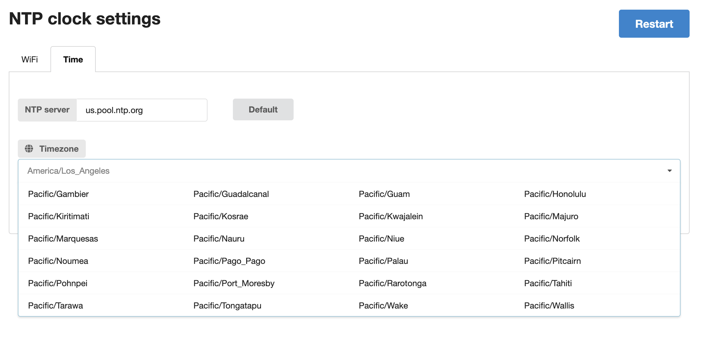
  5. Settings via WiFi AP mode and a web page.

Pictures

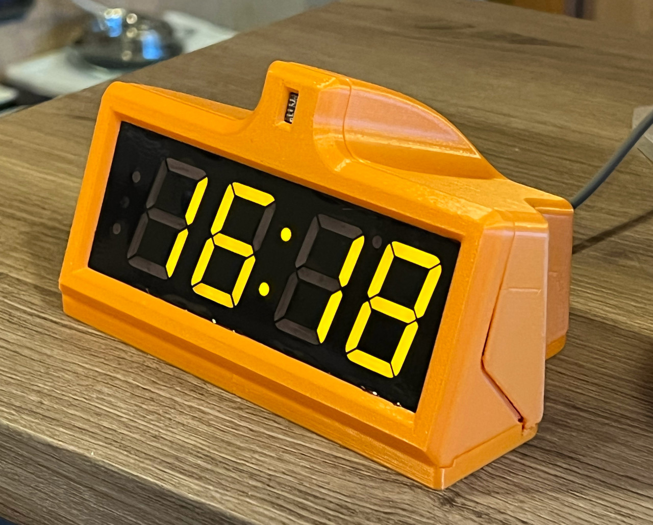
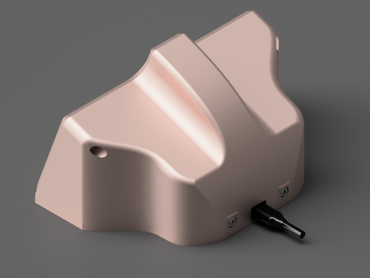
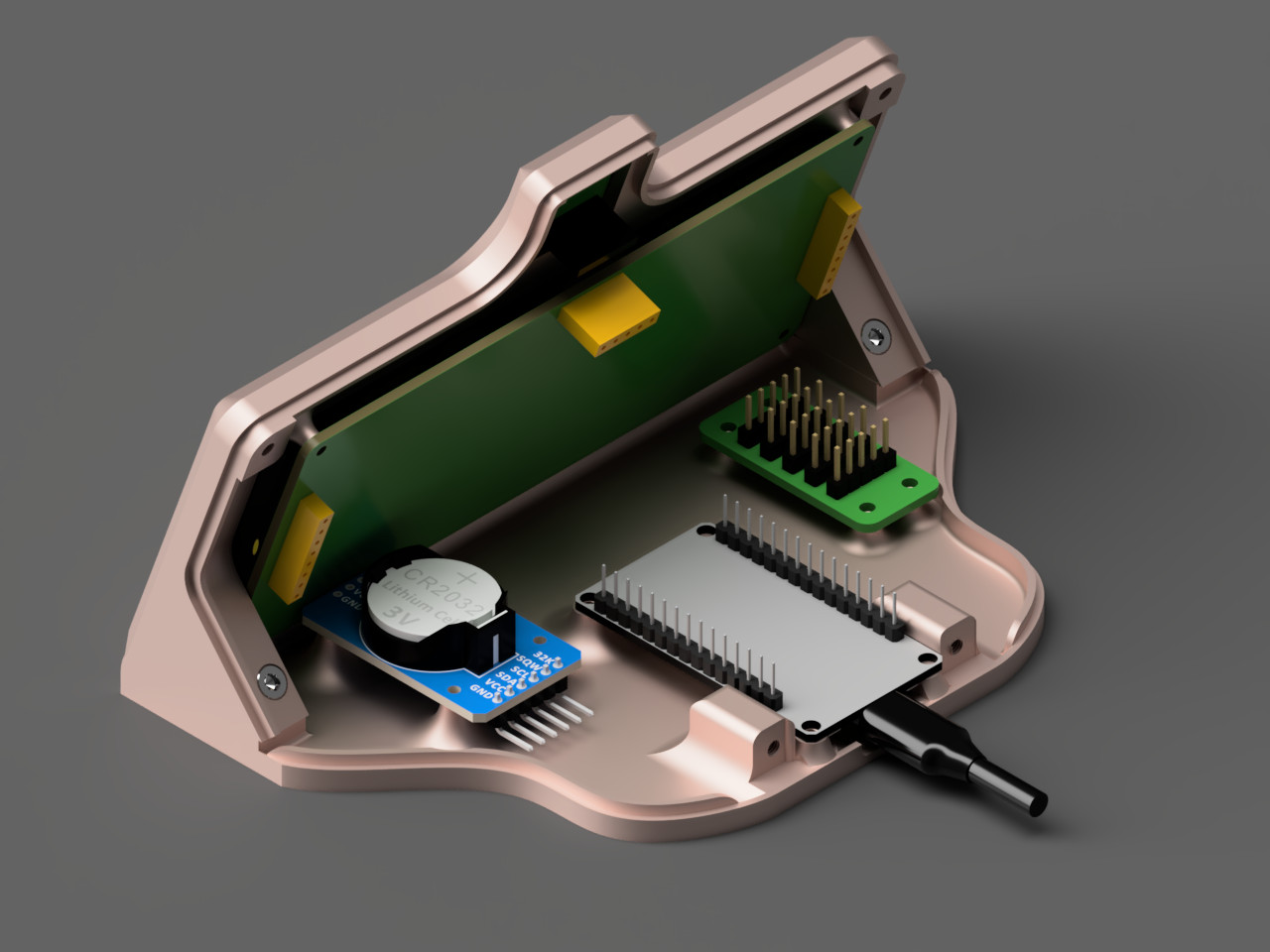
Front view Back view Inside view

Bill of materials

PartPrice
ESP32, Generic DevKit V1$8
Adafruit 1.2" 7-segment display$18
DS3231SN RTC module$18
Adafruit VEML7700 lux sensor$5
Custom I2C and power hub board$5
Jumper wires, Female-Female$2
M3, M2.5 and M2 bolts$5
3D printed plastic enclosure$8
Tint film (ex. for cars)$1
------------------------------------
Total$70

Building and running the device

  1. Manufacture I2C/Power hub using files from cad/i2c_header_x5. Don't forget 3.2K pull-up resistors.
  2. 3D print enclosure using files from cad/enclosure.
  3. Apply tint film to the display module.
  4. Assemble the device. Select appropriate screw diameter and length for each hole. Connect hub 5V to VIN in ESP32, ground to ground, 3.3V to 3.3V, SDA/SCL to appropriate ESP32 pins. Connect every component to the hub.
  5. Install ESP-IDF v4.4 - https://github.com/espressif/esp-idf/tree/release/v4.4 .
  6. Clone repository and init submodules recursively.
  7. Copy main/secrets.h from main/secrets.h.example and set your own setting inside.
  8. Using instructions from EPS-IDF, build and flash the firmware.

Changing settings after flashing firmware

  1. To change settings after flash, connect the device to power and press 'SET' button on the bottom.
  2. Device will create a WiFi AP with SSID looking like ntpclock-XXXXXXXX.
  3. The password will be shown scrolling on display.
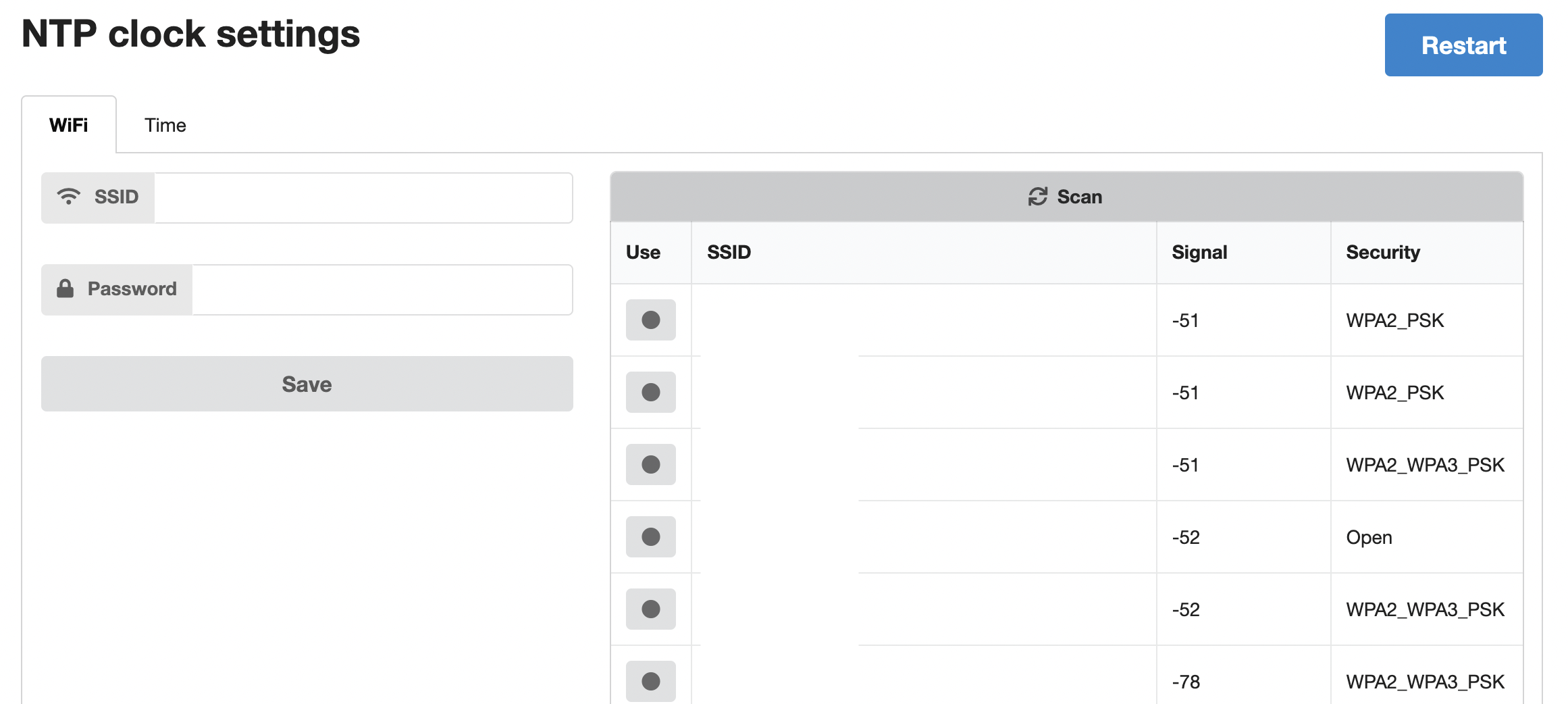
  4. Connect to AP and open http://192.168.4.1 .

UI wifi tab UI time tab

Parts

12
QtyValueFootprintReferences
5Conn_01x05_MaleConnector_PinHeader_2.54mm:PinHeader_1x05_P2.54mm_Vertical3V3, 5V1, GND1, SCL1, SDA1
24K7Resistor_SMD:R_0805_2012Metric_Pad1.20x1.40mm_HandSolderR0, R1

The 7 most common of 12 parts.

Questions

How big is the I2c header x5 PCB?

It measures 36.8 × 16.5 mm and has 2 copper layers, 1.6 mm thick.

What parts does the I2c header x5 use?

12 parts. The full list of its parts is on this page, with links to each part's symbol and footprint where PCBKit's library has them.

Where can I download the I2c header x5 KiCad files?

From the chudsaviet/ntpclock repository on GitHub, at the commit this page was made from: the board is cad/i2c_header_x5/i2c_header_x5.kicad_pcb. PCBKit opens the board in the browser, with nothing to install.

Can I use the I2c header x5 design in my own project?

Its repository states no licence, so its author keeps all rights: ask chudsaviet before reusing the design.

Similar boards

  • 2 layersNrf bga, the printed circuit board in 3D

    Nrf bga

    github-linguist/linguist

    Language Savant. If your repository's language is being reported incorrectly, send us a pull request!

    12 parts14kMIT
  • 2 layers66.9 × 74.5 mmDeskHop, the printed circuit board in 3D

    DeskHop

    hrvach/deskhop

    Fast Desktop Switching Device

    12 parts7.9kGPL-3.0
  • 2 layers40 × 15 mmSensors, the printed circuit board in 3D

    Sensors

    google/mozc-devices

    Circuit diagrams and firmware source code for Gboard DIY keyboards

    12 parts3kApache-2.0
  • 2 layers42.7 × 56.5 mmTle6240 driver, the printed circuit board in 3D

    Tle6240 driver

    rusefi/rusefi

    rusefi - GPL internal combustion engine control unit

    12 parts1.2k
  • 2 layers49 × 25 mm5v boost regulator, the printed circuit board in 3D

    5v boost regulator

    hackclub/OnBoard

    💡 Join 1,000 teenagers and make your first PCB with a $100 grant!

    12 parts915
  • 2 layers28.3 × 10.3 mmTap Photosensor PCB, the printed circuit board in 3D

    Tap Photosensor PCB

    VoronDesign/Voron-Tap

    Tap is a nozzle-based z-probe for the V2 and Trident printer designs. The entire toolhead moves to trigger an optical switch. Tap offers many advantages:

    12 parts716GPL-3.0
  • 2 layers25.4 × 70.4 mmTpmsniffer, the printed circuit board in 3D

    Tpmsniffer

    stacksmashing/pico-tpmsniffer

    A simple, very experimental TPM sniffer for LPC bus

    12 parts696