

2 layers103 × 30.5 mm

 christrotter/optical-encoder-pcb
A standalone pcb for ploopy's optical encoder design.
Optical encoder pcb is an open-source printed circuit board by christrotter, from the christrotter/optical-encoder-pcb repository on GitHub, published under the MIT licence. It is a 2-layer board of 27.5 × 47.6 mm with 9 parts on 16 nets, routed with 36 tracks and 9 vias.
It is built around the XZTHI56W-1 and PT26-51B/TR8. Its parts include 4 resistors, 2 ICs, 2 diodes and 1 connector.
A standalone pcb for Ploopy's optical encoder design.
I decided not to go ahead with this mainly because QMK doesn't really support quadrature and custom encoder drivers simultaneously (and why would they? - so bougie). Also, the infrared leds are not in stock.
The theory was that I'd use the optical encoder for the mk20's 'ring' encoder, as it'd have less operating friction.
Anyways, I think the basics here would work - obviously I spent very little time on the pcb design.
Pretty simple - until you get to the maths and code.
Basically you have power, ground, analog1, analog2. When the LED light is interrupted by the wheel, the analog input goes low and thus the computer can do something about it. Your polling code looks at the analog inputs and determines what to do based on the combinations of on/off received over a time period.
I also used a VIK connector cuz why not: https://github.com/sadekbaroudi/vik/
Fun sidenote - the silicone surface on their scroll wheel is actually a silicone ring (on Aliexpress, search 'silicone ring fish scale').
https://www.eeworldonline.com/rotary-encoders-part-1-optical-encoders/ https://github.com/ploopyco/qmk_firmware/blob/master/keyboards/ploopyco/common/opt_encoder_simple.c https://github.com/ploopyco/qmk_firmware/blob/master/keyboards/ploopyco/ploopyco.c#L101 https://github.com/ploopyco/classic-trackball/tree/master/hardware/Electronics/Schematics
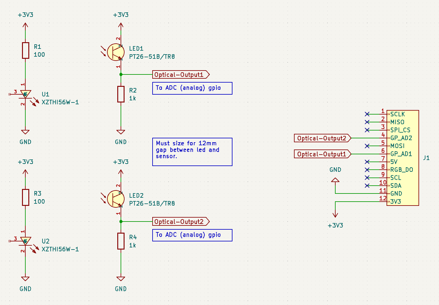
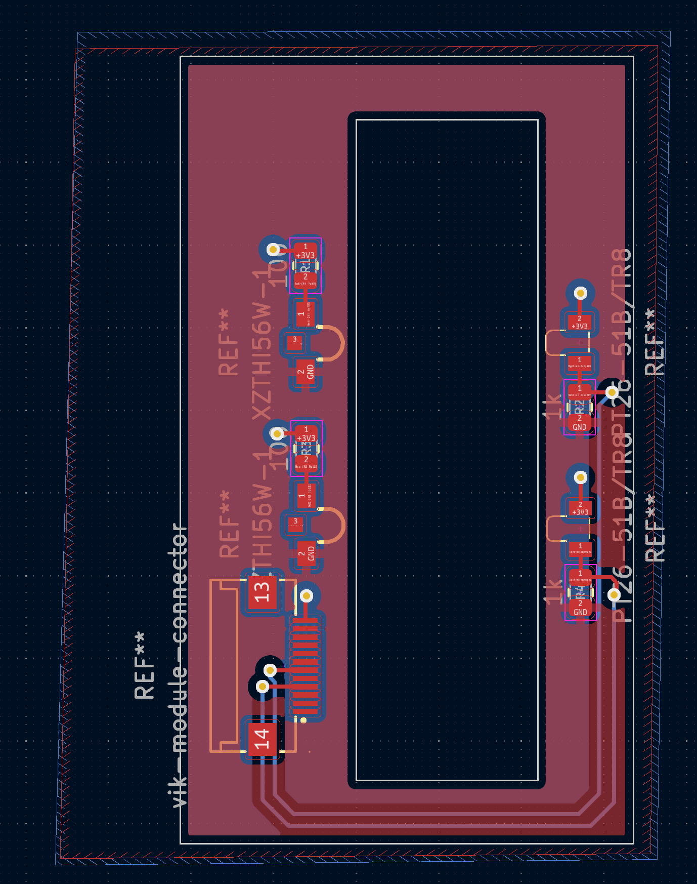
| Qty | Value | Footprint | References |
|---|---|---|---|
| 2 | 100 | Resistor_SMD:R_0805_2012Metric | R1, R3 |
| 2 | 1k | Resistor_SMD:R_0805_2012Metric | R2, R4 |
| 2 | PT26-51B/TR8 | MyKicadFootprints:OPTO-SMD_PT26-51B-TR8 | LED1, LED2 |
| 2 | XZTHI56W-1 | MyKicadFootprints:LED-SMD_3P-L3.0-W2.5 | U1, U2 |
| 1 | vik-module-connector | MyKicadFootprints:FPC-SMD_12P-P0.50_HCTL_XW05202-120R-00 | J1 |
It measures 27.5 × 47.6 mm and has 2 copper layers, 1.6 mm thick.
9 parts, built around the XZTHI56W-1 and PT26-51B/TR8. The full list of its parts is on this page, with links to each part's symbol and footprint where PCBKit's library has them.
From the christrotter/optical-encoder-pcb repository on GitHub, at the commit this page was made from: the board is optical-encoder-pcb.kicad_pcb and its schematic optical-encoder-pcb.kicad_sch. PCBKit opens the board in the browser, with nothing to install.
Its repository publishes it under the MIT licence: you may reuse it on that licence's terms (keep the author's notice, and for a copyleft licence share your changes alike).


FrameworkComputer/ExpansionCards
Reference designs and documentation to create Expansion Cards for the Framework Laptop

VoronDesign/Voron-Hardware
Cool Hardware designed by the Voron Design group

hackclub/OnBoard
💡 Join 1,000 teenagers and make your first PCB with a $100 grant!


adamws/kicad-kbplacer
KiCad plugin for automatic keyboard's key placement and routing