2 layers232.8 × 204.2 mm

 christal87/hardmpu
HardMPU PCB design based on the original schematic
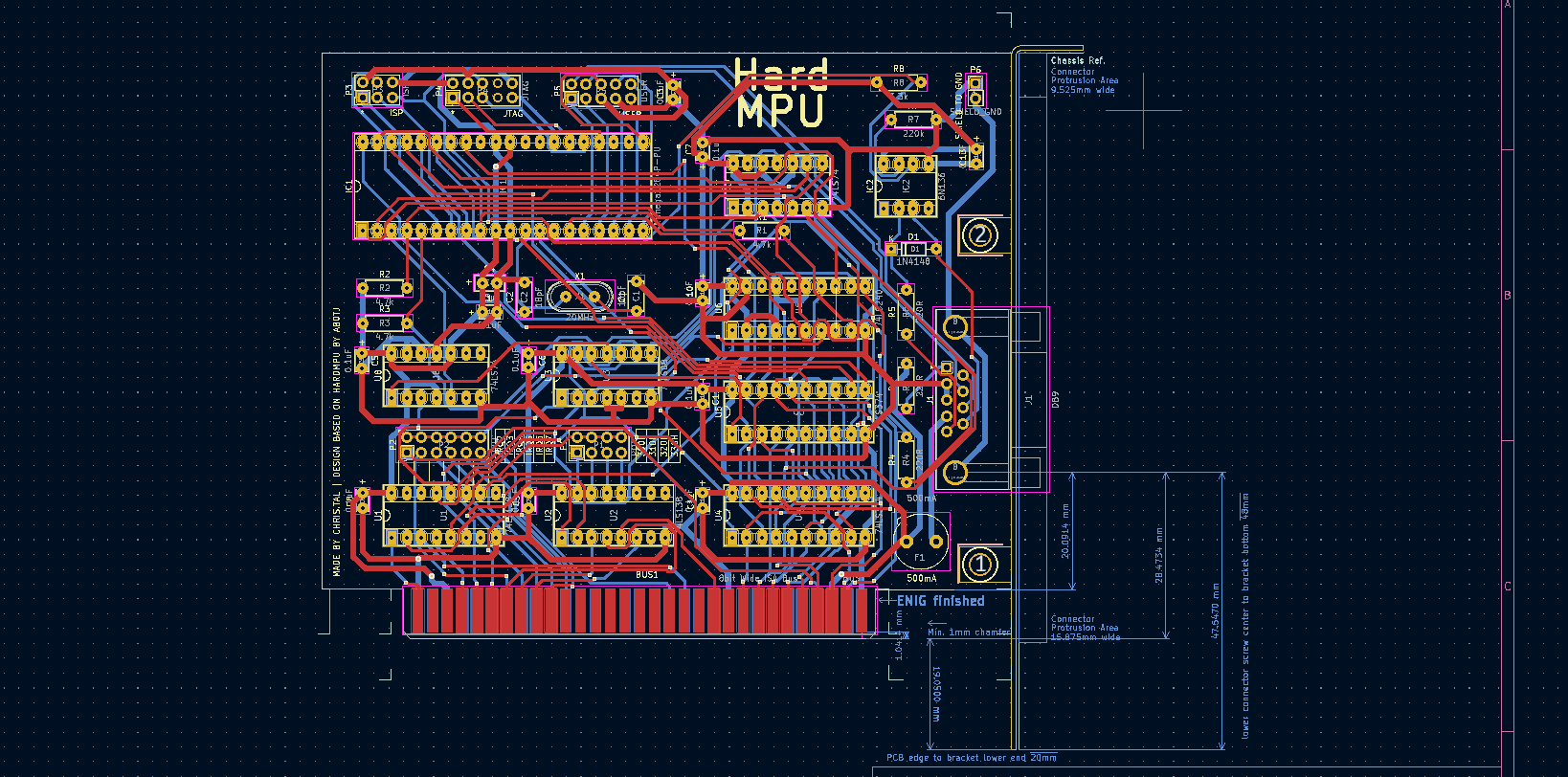
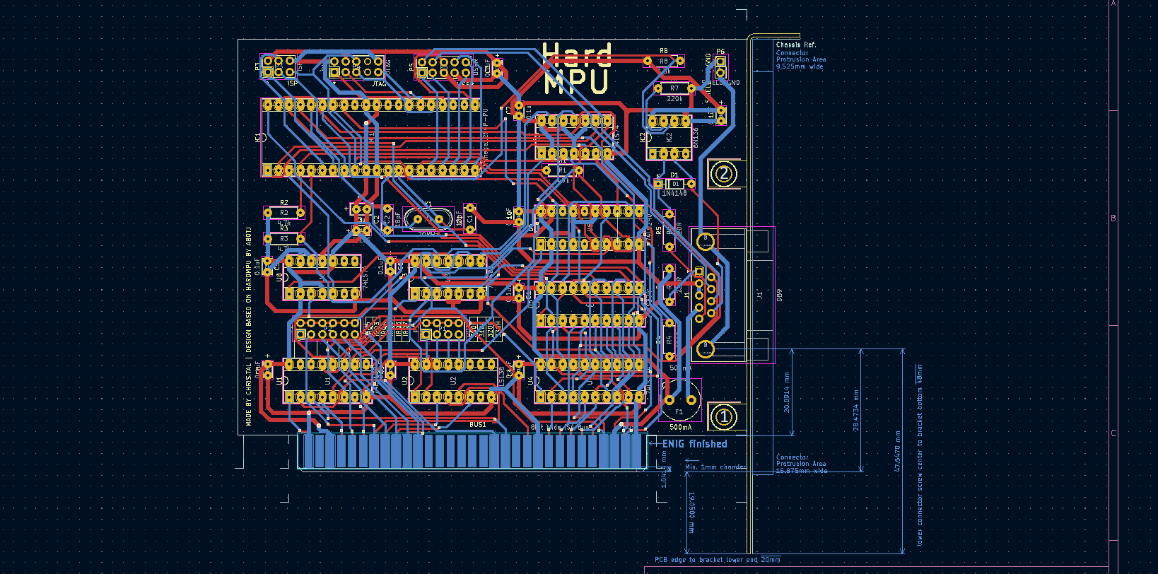
Hardmpu is an open-source printed circuit board by christal87, from the christal87/hardmpu repository on GitHub, published under the GPL-3.0 licence. It is a 2-layer board of 118.5 × 100.4 mm with 44 parts on 86 nets, routed with 1,279 tracks and 83 vias.
It is built around the ATMEGA1284P-PU, 74LS240DC and 74LS374PC, with the 74LS74PC among its other parts. Its parts include 14 capacitors, 10 ICs, 8 resistors, 7 connectors and 1 diode. It belongs with the AVR (ATmega, ATtiny) boards of this library.


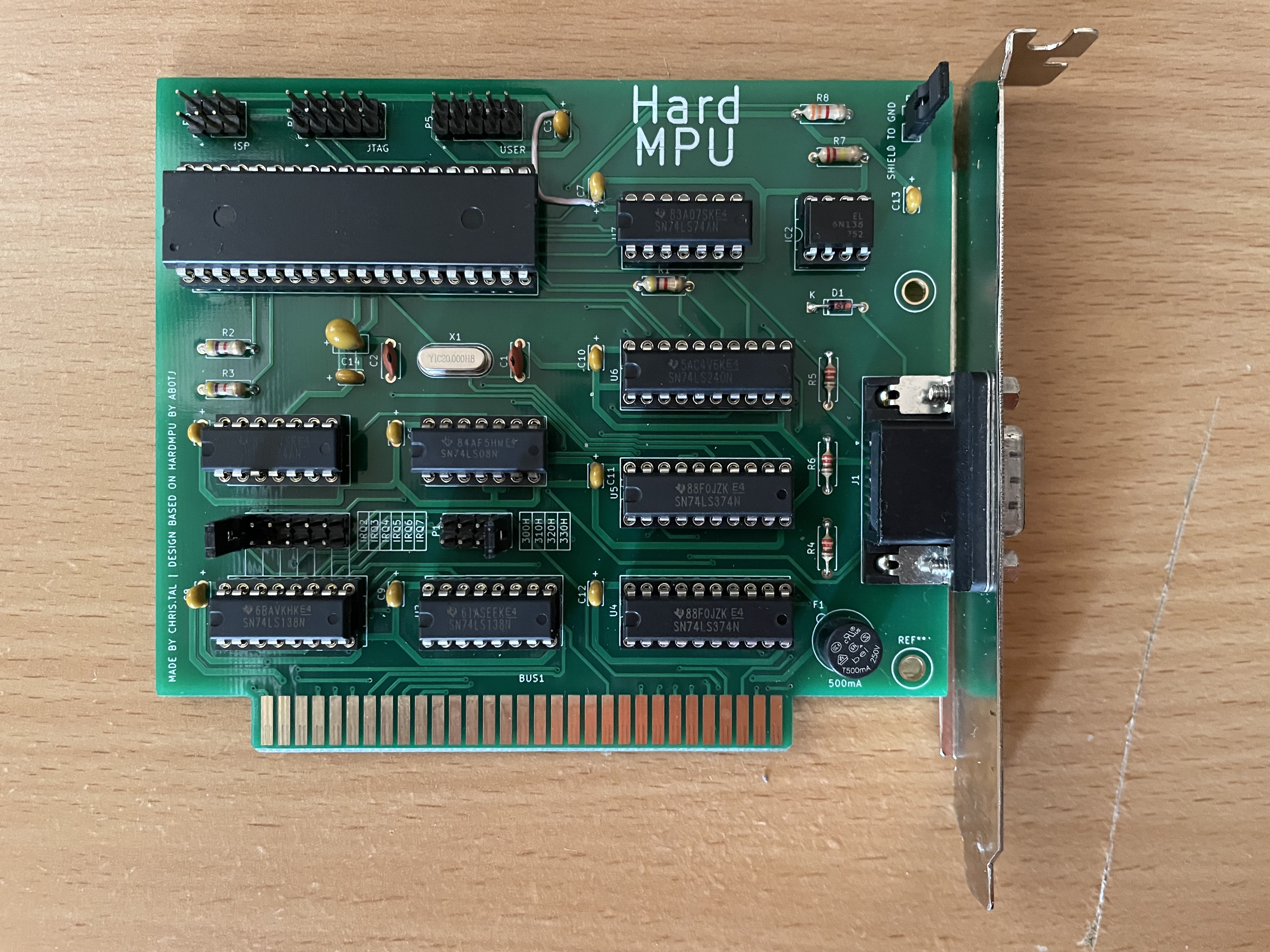
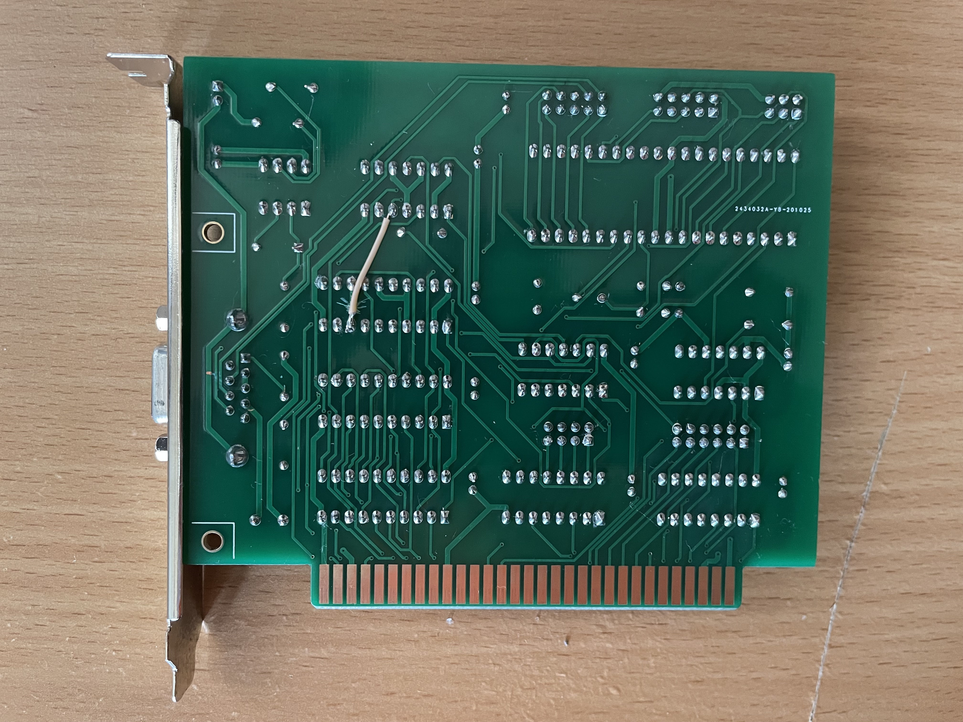
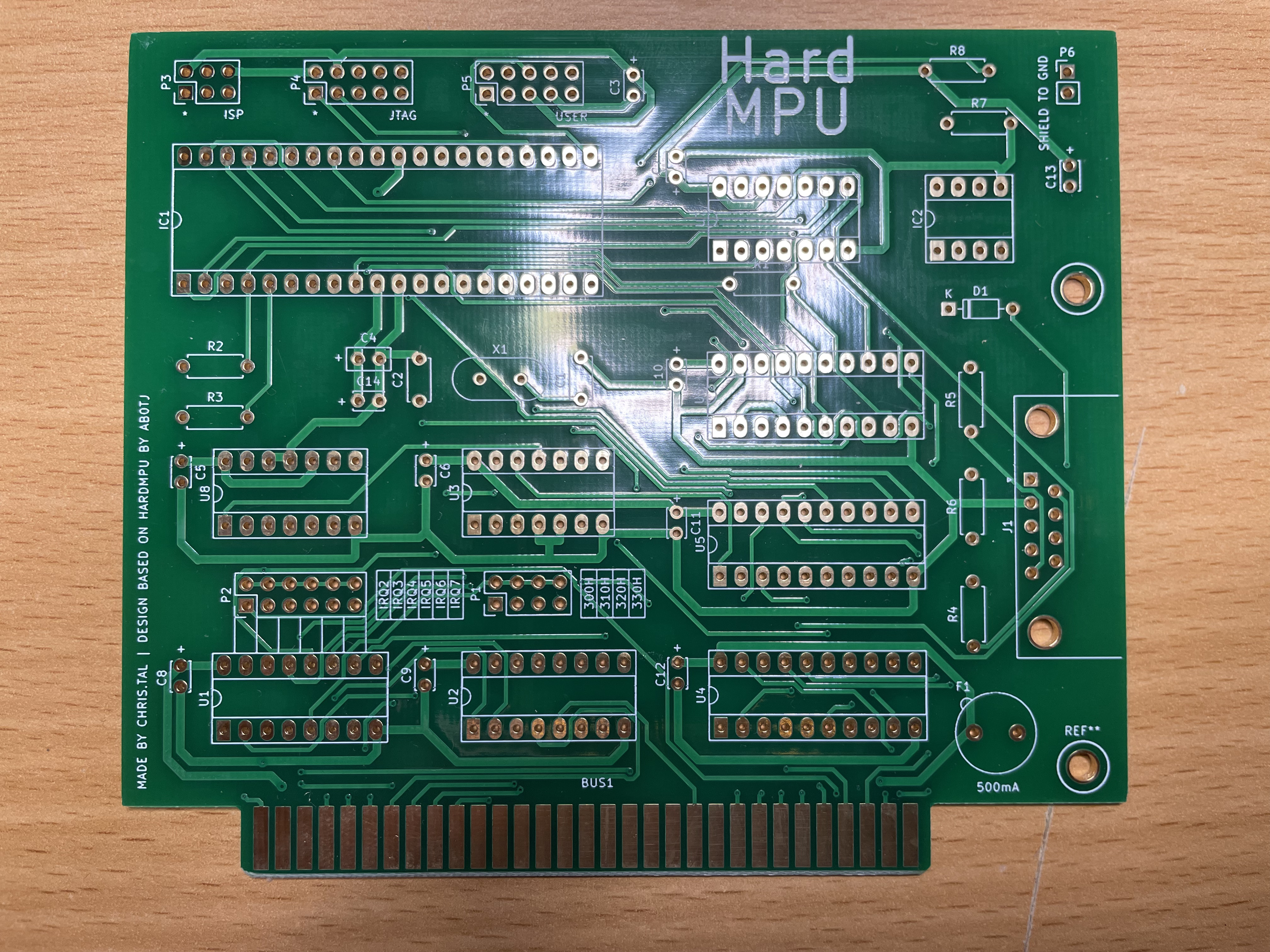
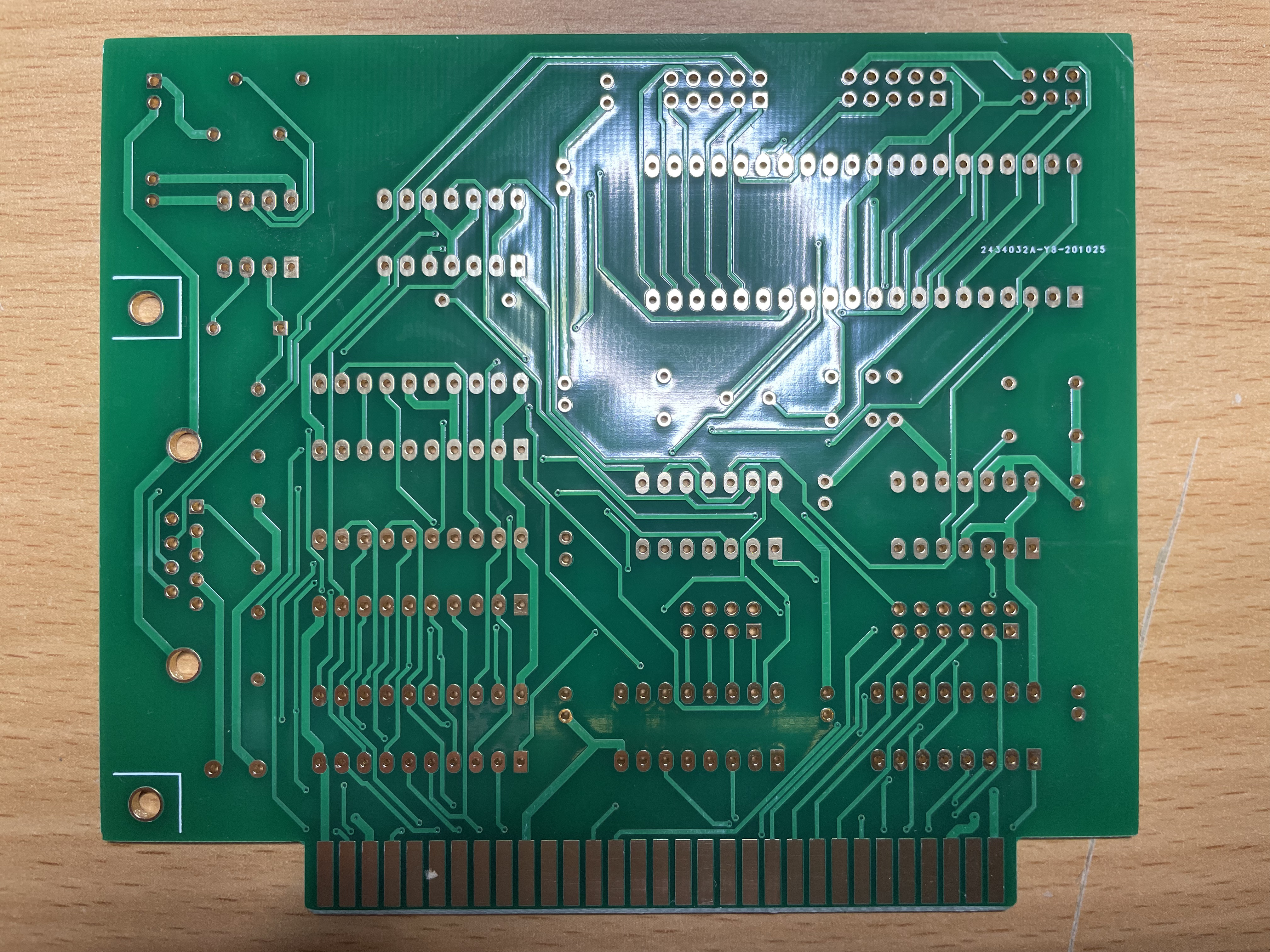
A HardMPU 8-bits wide ISA card PCB based on ab0tj's schematic. I was curious how ISA cards were designed back in the day and I'm also a retro PC enthusiast so I designed my own version a few years ago. I also used this project as an experiment to supplement and speed up a manual ECAD design flow using FreeRouting. After drawing an outline and placing components I let it run multiple iterations/optimizations then I chose one of it's suitable outputs as a template to refine manually afterwards. There are two label typos that slipped through invisibly ERC/DRC reporting stages which got corrected using bodge wires as a temporary fix (see photos). I've chosen an I/O bracket backplate that seemed to be popular and was readily available from multiple sources on Aliexpress at design time. Just like the original project, this circuit design is covered by the GPL-3.0 license and is free for non-commercial use.
| Qty | Value | Footprint | References |
|---|---|---|---|
| 11 | 0.1uF | Capacitor_THT:C_Disc_D3.4mm_W2.1mm_P2.50mm | C3, C5, C6, C7, C8, C9, C10, C11, C12, C13, C14 |
| 3 | 220R | Resistor_THT:R_Axial_DIN0207_L6.3mm_D2.5mm_P7.62mm_Horizontal | R4, R5, R6 |
| 3 | 4.7k | Resistor_THT:R_Axial_DIN0207_L6.3mm_D2.5mm_P7.62mm_Horizontal | R1, R2, R3 |
| 2 | 18pF | Capacitor_THT:C_Disc_D5.0mm_W2.5mm_P5.00mm | C1, C2 |
| 2 | 74LS138 | Package_DIP:DIP-16_W7.62mm_Socket_LongPads | U1, U2 |
| 2 | 74LS374 | Package_DIP:DIP-20_W7.62mm_Socket_LongPads | U4, U5 |
| 2 | 74LS74 | Package_DIP:DIP-14_W7.62mm_Socket_LongPads | U7, U8 |
| 1 | 1N4148 | Diode_THT:D_DO-35_SOD27_P7.62mm_Horizontal | D1 |
| 1 | 20MHz | Crystal:Crystal_HC49-U_Vertical | X1 |
| 1 | 220k | Resistor_THT:R_Axial_DIN0207_L6.3mm_D2.5mm_P7.62mm_Horizontal | R7 |
| 1 | 3.3k | Resistor_THT:R_Axial_DIN0207_L6.3mm_D2.5mm_P7.62mm_Horizontal | R8 |
| 1 | 33uF | Capacitor_THT:C_Disc_D5.0mm_W2.5mm_P2.50mm | C4 |
| 1 | 500mA | Fuse:Fuseholder_TR5_Littelfuse_No560_No460 | F1 |
| 1 | 6N136 | Package_DIP:DIP-8_W7.62mm_Socket_LongPads | IC2 |
| 1 | 74LS08 | Package_DIP:DIP-14_W7.62mm_Socket_LongPads | U3 |
| 1 | 74LS240 | Package_DIP:DIP-20_W7.62mm_Socket_LongPads | U6 |
| 1 | 8bit Wide ISA Bus | Connector_PCBEdge:ISA_CARD_EDGE_CONNECTOR_8BIT_Rev0 | BUS1 |
| 1 | ATmega1284P-PU | Package_DIP:DIP-40_W15.24mm_Socket_LongPads | IC1 |
| 1 | DB9 | Connector_Dsub:DSUB-9_Female_Horizontal_P2.77x2.84mm_EdgePinOffset7.70mm_Housed_MountingHolesOffset9.12mm | J1 |
| 1 | IRQ | Connector_PinHeader_2.54mm:PinHeader_2x06_P2.54mm_Vertical | P2 |
| 1 | ISP | Connector_PinHeader_2.54mm:PinHeader_2x03_P2.54mm_Vertical | P3 |
| 1 | JTAG | Connector_PinHeader_2.54mm:PinHeader_2x05_P2.54mm_Vertical | P4 |
| 1 | PORT | Connector_PinHeader_2.54mm:PinHeader_2x04_P2.54mm_Vertical | P1 |
| 1 | SHIELD_GND | Connector_PinHeader_2.54mm:PinHeader_1x02_P2.54mm_Vertical | P6 |
| 1 | USER | Connector_PinHeader_2.54mm:PinHeader_2x05_P2.54mm_Vertical | P5 |
The 43 most common of 44 parts.


lynchaj/duodyne
Duodyne is a hobbyist retrocomputer system designed to run ROMWBW. It is comprised of modules on a system bus


roberto314/GIMIX_reproduction
Reproducing SS-50 and SS-30 cards and GIMIX Ghost Case and Mainboard
It measures 118.5 × 100.4 mm and has 2 copper layers, 1.6 mm thick.
44 parts, built around the ATMEGA1284P-PU, 74LS240DC, 74LS374PC and 74LS74PC. The full list of its parts is on this page, with links to each part's symbol and footprint where PCBKit's library has them.
From the christal87/hardmpu repository on GitHub, at the commit this page was made from: the board is HardMPU.kicad_pcb. PCBKit opens the board in the browser, with nothing to install.
Its repository publishes it under the GPL-3.0 licence: you may reuse it on that licence's terms (keep the author's notice, and for a copyleft licence share your changes alike).