2 layers66.9 × 110 mm
Kitchen clock
chof747/kitchen-clock
This project is building a kitchen glock with the following functions:
74 parts

 chof747/mcu-bat-power
Battery power board for MCU basis
Mcu bat power is an open-source printed circuit board by chof747, from the chof747/mcu-bat-power repository on GitHub, published under the CC0-1.0 licence. It is a 2-layer board of 58.6 × 90.9 mm with 59 parts on 36 nets, routed with 331 tracks and 41 vias.
It is built around the MT3608, CN3058E and HY2112-CB, with the BH-18650-B1BA002, FS8205 and SS34A among its other parts. Its parts include 14 resistors, 5 capacitors, 5 diodes, 5 connectors and 4 ICs. It belongs with the power boards of this library.


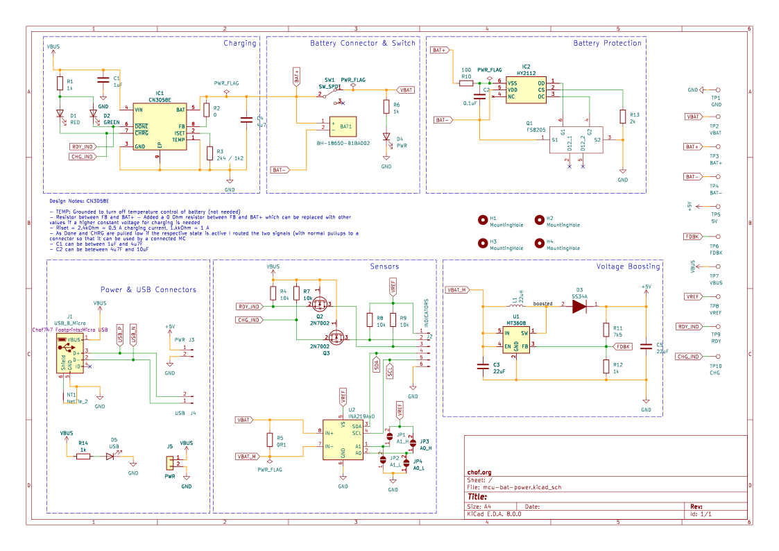
Battery power board for 5v compatible MCU boards featuring a LiFePo4 Holder
This project is a battery supplied power circuitry to supply microcontroller projects with 5V battery power + the ability to charge and protect a LiFePo4 battery. In addition breakout for the USB data lines, voltage and current measurement as well as the sensing pins of the charging circuit are added so that a proper power management from the microcontroller on an attached board is possible.
The concept of the board is to act as an add on board for a microcontroller board in a way that it can work for several battery powered projects.
The idea is based on a Great Scott's video and materials of a DIY LiPo Charge/Protect/5V Boost Circuit
This board includes a:

| Qty | Value | Footprint | References |
|---|---|---|---|
| 4 | 10k | Resistor_SMD:R_0603_1608Metric_Pad0.98x0.95mm_HandSolder | R4, R7, R8, R9 |
| 4 | 1k | Resistor_SMD:R_0603_1608Metric_Pad0.98x0.95mm_HandSolder | R1, R6, R12, R14 |
| 4 | MountingHole | Chof747 Footprints:MountingHole_3.2mm_M3-smallBorder | H1, H2, H3, H4 |
| 2 | 22uF | Capacitor_SMD:C_1206_3216Metric_Pad1.33x1.80mm_HandSolder | C3, C5 |
| 2 | 2N7002 | Package_TO_SOT_SMD:SOT-23 | Q2, Q3 |
| 1 | 0 | Resistor_SMD:R_0603_1608Metric_Pad0.98x0.95mm_HandSolder | R2 |
| 1 | 0.1uF | Capacitor_SMD:C_0603_1608Metric_Pad1.08x0.95mm_HandSolder | C2 |
| 1 | 0R1 | Resistor_SMD:R_2512_6332Metric_Pad1.40x3.35mm_HandSolder | R5 |
| 1 | 100 | Resistor_SMD:R_0603_1608Metric_Pad0.98x0.95mm_HandSolder | R10 |
| 1 | 1uF | Capacitor_SMD:C_0603_1608Metric_Pad1.08x0.95mm_HandSolder | C1 |
| 1 | 22uH | Chof747 Footprints:SMD0740 | L1 |
| 1 | 2k | Resistor_SMD:R_0603_1608Metric_Pad0.98x0.95mm_HandSolder | R13 |
| 1 | 2k4 / 1k2 | Resistor_SMD:R_0603_1608Metric_Pad0.98x0.95mm_HandSolder | R3 |
| 1 | 4u7 | Capacitor_SMD:C_0603_1608Metric_Pad1.08x0.95mm_HandSolder | C4 |
| 1 | 5V | TestPoint:TestPoint_Pad_2.0x2.0mm | TP5 |
| 1 | 7k5 | Resistor_SMD:R_0603_1608Metric_Pad0.98x0.95mm_HandSolder | R11 |
| 1 | A0_H | Jumper:SolderJumper-2_P1.3mm_Open_RoundedPad1.0x1.5mm | JP3 |
| 1 | A0_L | Jumper:SolderJumper-2_P1.3mm_Open_RoundedPad1.0x1.5mm | JP4 |
| 1 | A1_H | Jumper:SolderJumper-2_P1.3mm_Open_RoundedPad1.0x1.5mm | JP1 |
| 1 | A1_L | Jumper:SolderJumper-2_P1.3mm_Open_RoundedPad1.0x1.5mm | JP2 |
| 1 | BAT+ | TestPoint:TestPoint_Pad_2.0x2.0mm | TP3 |
| 1 | BAT- | TestPoint:TestPoint_Pad_2.0x2.0mm | TP4 |
| 1 | BH-18650-B1BA002 | Chof747 Footprints:BH18650B1BA002 | BAT1 |
| 1 | CHG | TestPoint:TestPoint_Pad_2.0x2.0mm | TP10 |
| 1 | CN3058E | Chof747 Footprints:SOIC127P600X175-9N | IC1 |
| 1 | FDBK | TestPoint:TestPoint_Pad_2.0x2.0mm | TP6 |
| 1 | FS8205 | Chof747 Footprints:FS8205 | Q1 |
| 1 | GND | TestPoint:TestPoint_Pad_2.0x2.0mm | TP1 |
| 1 | GREEN | LED_SMD:LED_0603_1608Metric_Pad1.05x0.95mm_HandSolder | D2 |
| 1 | HY2112 | Chof747 Footprints:SOT95P280X145-6N | IC2 |
| 1 | INA219AxD | Package_SO:SOIC-8_3.9x4.9mm_P1.27mm | U2 |
| 1 | INDICATORS | Connector_PinHeader_2.54mm:PinHeader_1x06_P2.54mm_Horizontal | J2 |
| 1 | LOGO | Chof747 Logos:LOGO small | G*** |
| 1 | MT3608 | Package_TO_SOT_SMD:SOT-23-6 | U1 |
| 1 | NetTie_2 | NetTie:NetTie-2_SMD_Pad0.5mm | NT1 |
| 1 | PWR | LED_SMD:LED_0603_1608Metric_Pad1.05x0.95mm_HandSolder | D4 |
| 1 | PWR | Chof747_Connectors:pad_1x2_1.5mmx3mm | J5 |
| 1 | PWR | Connector_PinHeader_2.54mm:PinHeader_1x02_P2.54mm_Horizontal | J3 |
| 1 | RDY | TestPoint:TestPoint_Pad_2.0x2.0mm | TP9 |
| 1 | RED | LED_SMD:LED_0603_1608Metric_Pad1.05x0.95mm_HandSolder | D1 |
| 1 | SS34A | Chof747 Footprints:DIOM5026X262N | D3 |
| 1 | SW_SPDT | Chof747 Footprints:Slide-switch-SS-12D11L7 | SW1 |
| 1 | USB | Connector_PinHeader_2.54mm:PinHeader_1x02_P2.54mm_Horizontal | J4 |
| 1 | USB | LED_SMD:LED_0603_1608Metric_Pad1.05x0.95mm_HandSolder | D5 |
| 1 | USB_B_Micro | Chof747 Footprints:Micro USB | J1 |
| 1 | VBAT | TestPoint:TestPoint_Pad_2.0x2.0mm | TP2 |
| 1 | VBUS | TestPoint:TestPoint_Pad_2.0x2.0mm | TP7 |
| 1 | VREF | TestPoint:TestPoint_Pad_2.0x2.0mm | TP8 |
chof747/kitchen-clock
This project is building a kitchen glock with the following functions:

prichert17/PAMI
Ce dépôt documente le projet PAMI (Petit Actionneur Motorisé Indépendant) sur lequel j'ai travaillé pendant un an, dans le cadre de la coupe Eurobot 2026.


petnica-rac-seminari/BCD-0o27-Tetris
The BalcCon Cyberdeck 0o27 (BCD-0o27) comes with a development framework that makes it easier to add functionality to the cyberdeck.


EdgeCoil/wiegand-bridge
ESP32-S3 Wiegand reader bridge for Home Assistant: 4-layer board, BOM and ESPHome firmware.

essensys-hub/essensys-i2c-etoile-0v
Carte qui relie le boîtier principal (BP, carte SC944D) aux boîtiers auxiliaires (BA1 SC940D, BA2 SC941C, BA3 SC942C) d'une installation Essensys en étoile autour d'un plan 0 V commun, à la place du chaînage d'origine.

pho/esp32-lifepo4-board
Kicad pcb design of a minimal board with an ESP32 and a LiFePo4 charging circuit
It measures 58.6 × 90.9 mm and has 2 copper layers, 1.6 mm thick.
59 parts, built around the MT3608, CN3058E, HY2112-CB and BH-18650-B1BA002. The full list of its parts is on this page, with links to each part's symbol and footprint where PCBKit's library has them.
From the chof747/mcu-bat-power repository on GitHub, at the commit this page was made from: the board is mcu-bat-power.kicad_pcb and its schematic mcu-bat-power.kicad_sch. PCBKit opens the board in the browser, with nothing to install.
Its repository publishes it under the CC0-1.0 licence: you may reuse it on that licence's terms (keep the author's notice, and for a copyleft licence share your changes alike).