2 layers
Smartmeter IR ReaderOnly V12
greenMikeEU/shrdzm
SHRDZM (just a name, not an acronym) is an ESP8285/ESP8266 based sensor and actor integration platform.
18 partsGPL-3.0

 chof747/smartmeter-ir-reader
This is an implementation of the smart reader concept created by volkszaehler.org.
Smartmeter ir reader is an open-source printed circuit board by chof747, from the chof747/smartmeter-ir-reader repository on GitHub, published under the CC0-1.0 licence. It is a 2-layer board of 27 × 34.7 mm with 16 parts on 13 nets, routed with 92 tracks and 8 vias.
It is built around the SN74LVC1G17DBVR, BAT46W and S8550, with the SFH 309 and SS8050-G among its other parts. Its parts include 4 resistors, 3 capacitors, 3 transistors, 2 ICs and 2 diodes.


This is an implementation of the smart reader concept created by volkszaehler.org.
It has been modified as follows:
This board is intended to interface with a Microcontroller unit via an RJ11 connector.
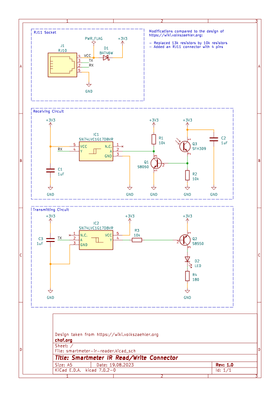
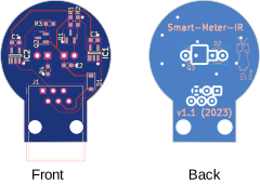
| Qty | Value | Footprint | References |
|---|---|---|---|
| 3 | 10k | Resistor_SMD:R_0603_1608Metric_Pad0.98x0.95mm_HandSolder | R1, R2, R3 |
| 3 | 1uF | Capacitor_SMD:C_0603_1608Metric_Pad1.08x0.95mm_HandSolder | C1, C2, C3 |
| 2 | SN74LVC1G17DBVR | Chof747 Footprints:SOT95P270X145-5N | IC1, IC2 |
| 1 | 180 | Resistor_SMD:R_0603_1608Metric_Pad0.98x0.95mm_HandSolder | R4 |
| 1 | BAT46W | Diode_SMD:D_SOD-123 | D1 |
| 1 | LED | LED_THT:LED_D3.0mm_Clear | D2 |
| 1 | LOGO | Chof747 Logos:LOGO small | G*** |
| 1 | RJ10 | Connector_RJ:RJ12_Amphenol_54601 | J1 |
| 1 | S8550 | Package_TO_SOT_SMD:SOT-23 | Q2 |
| 1 | SFH309 | LED_THT:LED_D3.0mm_Clear | Q3 |
| 1 | SS8050-G | Package_TO_SOT_SMD:SOT-23 | Q1 |
It measures 27 × 34.7 mm and has 2 copper layers, 1.6 mm thick.
16 parts, built around the SN74LVC1G17DBVR, BAT46W, S8550 and SFH 309. The full list of its parts is on this page, with links to each part's symbol and footprint where PCBKit's library has them.
From the chof747/smartmeter-ir-reader repository on GitHub, at the commit this page was made from: the board is smartmeter-ir-reader.kicad_pcb and its schematic smartmeter-ir-reader.kicad_sch. PCBKit opens the board in the browser, with nothing to install.
Its repository publishes it under the CC0-1.0 licence: you may reuse it on that licence's terms (keep the author's notice, and for a copyleft licence share your changes alike).
greenMikeEU/shrdzm
SHRDZM (just a name, not an acronym) is an ESP8285/ESP8266 based sensor and actor integration platform.


www-ShapeLabs-de/sgm4_to_mqtt
ESP8266 electricity meter reading head for SGM-C4 meter with homeassistant mqtt-discovery

vich-667/OptolinkDuoBlock
This project was created to have local access to the viessmann heating system to monitor and control and have the vitoconnect still working.


xPiTi/pillex-main
Submission files for MSc project - Pillex - pill dispensing device

GR3Y-SCALE/EGB220-A10
General repository for CAD designs, meeting docs, planners and code